VAXserver/VAX 4000-series System Conversion Guide Order Number: EK-VM430-CG. C01 October 1992 This is a revised manual.
October 1992 The information in this document is subject to change without notice and should not be construed as a commitment by Digital Equipment Corporation. Digital Equipment Corporation assumes no responsibility for any errors that may appear in this document. The software described in this document is furnished under a license and may be used or copied only in accordance with the terms of such license.
Contents Preface . . . . . . . . . . . . . . . . . . . . . . . . . . . . . . . . . . . . . . . . . . . . . . . . . . . . . vii 1 VAXserver/MicroVAX 3300/3400 Conversion 1.1 1.2 1.3 1.4 Summary of Conversion . Unpacking the Kit . . . . . Before Installing the Kit Installing the Kit . . . . . . . . . . . . . . . . . . . . . . . . . . . . . . . . . . . . . . . . . . . . . . . . . . . . . . . . . . . . . . . . . . . . . . . . . . . . . . . . . . . . . . . . . . . . . . . . . . . . . .
5 VAX/VAXserver 4000-300, -400, and -500 Conversion 5.1 5.2 5.3 5.4 5.5 5.6 5.6.1 5.6.2 5.6.3 5.6.4 Summary of Conversion . . . . . . . . . . . . . . . . . . . . . . . . . System Requirements . . . . . . . . . . . . . . . . . . . . . . . . . . Unpacking the Kit . . . . . . . . . . . . . . . . . . . . . . . . . . . . . Before Installing the Kit . . . . . . . . . . . . . . . . . . . . . . . . Installing the Kit . . . . . . . . . . . . . . . . . . . . . . . . . . . . . .
3–2 3–3 3–4 3–5 3–6 4–1 4–2 4–3 4–4 4–5 5–1 5–2 5–3 5–4 5–5 5–6 5–7 Removing CPU I/O Panel Console Cable Removing CPU I/O Panel . . . . . . . . . . . . CPU and Memory Label Locations . . . . . Conversion Label Location . . . . . . . . . . . Medallion Location . . . . . . . . . . . . . . . . . Removing Console Cable . . . . . . . . . . . . Removing CPU I/O Panel . . . . . . . . . . . . Attaching CPU Labels . . . . . . . . . . . . . . Conversion and Serial Label Locations . Medallion Location . . . . . . . .
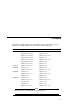
Preface The following table lists the conversion kits needed to upgrade the various VAXserver- and MicroVAX-series systems described in this guide. Kit Upgrade from... To...
Intended Audience This document is intended for Digital Services personnel and licensed self-maintenance customers. Customer Responsibilities Customers should not install the conversion kit unless they are qualified self-maintenance customers. Only qualified maintenance personnel should perform the installation procedure. If you are not a qualified self-maintenance customer, call Digital Services to schedule a system conversion.
Organization This document contains five chapters and one appendix: Chapter Description 1 Describes how to install the conversion kit 660XR-XX on a VAXserver 3300/3400 system or a MicroVAX 3300/3400 system. 2 Describes how to install the conversion kit 660XR-XX on a VAXserver 3500/3800 system or a MicroVAX 3500/3800 system. 3 Describes how to install the conversion kit 660XR-XX on a VAXserver 3600/3900 system or a MicroVAX 3600/3900 system.
Related Documents The following is a list of related documents: x Documentation Order Number BA440/BA430 Enclosure Maintenance EK-348AB-MG KA660 CPU System Maintenance EK-498AA-MG KA670 CPU System Maintenance EK-347AB-MG KA675/680/690 CPU System Maintenance EK-454AA-MG VMS License Management Utility Manual AA-LA33A-TE
1 VAXserver/MicroVAX 3300/3400 Conversion This chapter describes how to convert from a VAXserver 3300/3400 system to a VAXserver 4000-200 system and from a MicroVAX 3300/3400 system to a VAX 4000-200 system using a 660XR-XX conversion kit. Caution The MS650-AA memory module will not function with a KA660-XX CPU module. When a KA640 CPU module is removed and the system is converted to a KA660-XX system, install an MS650-BA (16-Mbyte) memory or MS650-BB (8-Mbyte) memory. 1.
VAXserver/MicroVAX 3300/3400 Conversion 1.1 Summary of Conversion 9. Remove the old CPU module. 10. Install the new KA660-AA/BA (M7626) CPU module. 11. Upgrade the old memory modules to MS650-BA/BB, if necessary. 12. Reconnect all CPU cables. 13. Reinstall the CPU I/O panel. 14. Reinstall the CPU I/O cover cables. 15. Replace the front panel. 16. Install the new medallion and labels. 17. Run diagnostics to verify system operation. 18. Have the customer verify that the system boots and operates correctly.
VAXserver/MicroVAX 3300/3400 Conversion 1.3 Before Installing the Kit 1.3 Before Installing the Kit Before installing the kit: 1. Have the customer back up the system software before the Digital Services representative arrives. It is the customer’s responsibility to back up the system software. 2. Turn on the system power and run diagnostics to verify system operation. 3. Turn off the system power before installing the kit. 1.4 Installing the Kit To install the conversion kit: 1.
VAXserver/MicroVAX 3300/3400 Conversion 1.
VAXserver/MicroVAX 3300/3400 Conversion 1.4 Installing the Kit 4. Remove the console cable as shown in Figure 1–2. 5. If the Ethernet cable is present, remove the Ethernet cable from the I/O panel. Caution Use the antistatic wrist strap and the antistatic mat when working with the modules.
VAXserver/MicroVAX 3300/3400 Conversion 1.4 Installing the Kit 6. Release the CPU I/O panel as shown in Figure 1–3. Disconnect the cable that connects the CPU module to the I/O panel, and set the panel aside. Figure 1–3 Removing CPU I/O Panel To Release: Push In and Turn Counterclockwise 1/4-Turn To Fasten: Push In and Turn Clockwise 1/4-Turn Attach Antistatic Wrist Strap to System Chassis MLO-002615 7. Disconnect the CPU module cables. 8. Remove the old CPU module from slot 1. 9.
VAXserver/MicroVAX 3300/3400 Conversion 1.4 Installing the Kit 10. If memory needs to be upgraded, remove the module covers from the remaining memory module slots. 11. Remove the 50-pin daisychain memory cable that connects the memory modules to the CPU module, if applicable. 12. Install the new memory modules, if applicable, and reconnect the 50-pin daisychain memory cable. 13. Reconnect the memory modules and DSSI cables to the CPU module. 14. Reconnect the CPU I/O panel and install over slots 1 and 2.
VAXserver/MicroVAX 3300/3400 Conversion 1.4 Installing the Kit Figure 1–4 CPU and Memory Label Locations MS650 BA/BB M7622 BA/BB KA660 A A/BA M7626 AA/BA MS650 B A/BB M7622 BA/BB Option MLO-003907 LJ-00487-TI0 18. Replace the front panel. 19. Turn on the system power and run system diagnostics to verify system operation.
VAXserver/MicroVAX 3300/3400 Conversion 1.4 Installing the Kit 20. Place the new serial label over the existing serial label, as shown in Figure 1–5 for a pedestal system. Figure 1–5 Conversion and Serial Label Location Hz W 50-60 670 708A Listed E.O.P. Equip. Made in U.S.A. Fabrique aux Etats-Unis Also classified by Underwriters Laboratories Inc. in accordance with IEC Publications 435 and 380. This epuipment complies with the requirements in Part 15 of FCC Rules for a Class A computing device.
VAXserver/MicroVAX 3300/3400 Conversion 1.4 Installing the Kit Note Two labels are shipped with the conversion kit. Install the JTT label, P/N 36-33180-18, for a BA213 enclosure; install the JTT label, P/N 36-33180-19, for a BA215 enclosure. 22. Attach the new logo model label over the existing logo model label as shown in Figure 1–6 for rack-mountable systems. 23. Attach the conversion label, as shown in Figure 1–5 for a pedestal system, and Figure 1–6 for a rack-mountable system.
VAXserver/MicroVAX 3300/3400 Conversion 1.4 Installing the Kit 24. Remove the old medallion by using a flat-blade screwdriver to lift the medallion off the front panel. 25. Attach the new medallion to the front panel as shown in Figure 1–7. Figure 1–7 Medallion Location VAXserver 4000-200 VAX 4000-200 MLO-002614 LJ-00486-TI0 26. Have the customer reinstall the system backup data. 27. Fill out the forms in Appendix A.
2 VAXserver/MicroVAX 3500/3800 Conversion This chapter describes how to convert from a VAXserver 3500/3800 system to a VAXserver 4000-200 system and from a MicroVAX 3500/3800 system to a VAX 4000-200 system using a 660XR-XX conversion kit. Caution The MS650–AA memory module will not function with a KA660–XX CPU module. When a KA650 or KA655 CPU module is removed and the system is converted to a KA660-XX system, do the following: 1. Install an MS650–BA (16-Mbyte) memory or MS650–BB (8-Mbyte) memory module.
VAXserver/MicroVAX 3500/3800 Conversion 2.1 Summary of Conversion 6. Remove the CPU I/O cover cables. 7. Remove the CPU I/O panel. 8. Remove the module cover from the KFQSA module. Remove the module covers from the memory slots, if memory needs to be upgraded. 9. Disconnect the CPU memory cable. 10. Remove the old CPU module. 11. Install the new KA660 (M7626) CPU module. 12. Upgrade the old memory modules to MS650-BA/BB, if necessary. 13. Reroute the internal DSSI cable, if applicable. 14.
VAXserver/MicroVAX 3500/3800 Conversion 2.2 Unpacking the Kit 2.2 Unpacking the Kit To unpack the kit: 1. Make sure there is no external damage to the shipping container, such as dents, holes, or crushed corners. 2. Unpack the conversion kit and check its contents against the shipping invoice. Caution Wear an antistatic wrist strap and use an antistatic mat during module handling to prevent static discharge and damage to modules.
VAXserver/MicroVAX 3500/3800 Conversion 2.4 Installing the Kit 2.4 Installing the Kit To install the conversion kit: 1. Turn the front panel key switch to the bottom position, lower the access door, and turn the power switch on the CPU box to off (O). 2. Turn off the system power to any expander boxes connected to the system. 3. Remove the front panel as shown in Figure 2–1.
VAXserver/MicroVAX 3500/3800 Conversion 2.4 Installing the Kit 4. If the external DSSI cable is used in the system, then disconnect it from the external connector on the media faceplate. 5. Remove the media faceplate as shown in Figure 2–2.
VAXserver/MicroVAX 3500/3800 Conversion 2.4 Installing the Kit 6. Remove the operator control panel (OCP) as shown in Figure 2–3.
VAXserver/MicroVAX 3500/3800 Conversion 2.4 Installing the Kit 7. Remove the console cable as shown in Figure 2–4. Caution Wear the antistatic wrist strap and use the antistatic mat when working with modules.
VAXserver/MicroVAX 3500/3800 Conversion 2.4 Installing the Kit 8. Release the CPU I/O panel as shown in Figure 2–5. Disconnect the cable that connects the CPU to the I/O panel, and set the panel aside. Figure 2–5 Removing CPU I/O Panel To Release: Push In and Turn Counterclockwise 1/4-Turn To Fasten: Push In and Turn Clockwise 1/4-Turn Attach Antistatic Wrist Strap to System Chassis MLO-002615 9. Disconnect the CPU module cables. 10. Remove the old CPU module from slot 1. 11.
VAXserver/MicroVAX 3500/3800 Conversion 2.4 Installing the Kit 12. Remove the module cover from the KFQSA module. Remove the module covers from the memory slots. 13. Disconnect the socket end of the internal DSSI cable that is connected to the KFQSA module. 14. Reroute the cable up through the notch at the left-front of the mass storage shelf. 15. Run the cable down through the space to the left of the tape drive as shown in Figure 2–6.
VAXserver/MicroVAX 3500/3800 Conversion 2.4 Installing the Kit 22. Install the new H3602 CPU I/O panel.
VAXserver/MicroVAX 3500/3800 Conversion 2.4 Installing the Kit 23. Attach the new CPU module label to the CPU I/O panel as shown in Figure 1–4. 24. Install the memory module covers. 25. Attach the new memory module labels to the memory module covers as shown in Figure 1–4. 26. Reconnect the cables to the CPU I/O panel. 27. Reinstall the OCP. 28. Reinstall the media faceplate. 29. If the external DSSI cable is used in the system, then reconnect it to the external connector on the media faceplate. 30.
VAXserver/MicroVAX 3500/3800 Conversion 2.4 Installing the Kit Figure 2–7 Conversion and Serial Label Locations Hz W To: By: Date: 50-60 670 Made in U.S.A. Fabrique aux Etats-Unis 708A Listed E.O.P. Equip. Also classified by Underwriters Laboratories Inc. in accordance with IEC Publications 435 and 380. This epuipment complies with the requirements in Part 15 of FCC Rules for a Class A computing device.
VAXserver/MicroVAX 3500/3800 Conversion 2.4 Installing the Kit 34. Attach the new logo model label over the existing logo model label as shown in Figure 2–8 for rack-mountable systems. 35. Attach the new conversion label as shown in Figure 2–7 for pedestal systems, and Figure 2–8 for rack-mountable systems.
VAXserver/MicroVAX 3500/3800 Conversion 2.4 Installing the Kit 36. Remove the old medallion using a flat-blade screwdriver to lift it off the front panel. Attach the new medallion as shown in Figure 2–9. Figure 2–9 Medallion Location VAX 4000-200 MLO-003643 LJ-00489-TI0 37. Have the customer reinstall the system backup data. 38. Fill out the forms in Appendix A.
3 VAXserver/MicroVAX 3600/3900 Conversion This chapter describes how to convert from a VAXserver 3600/3900 system to a VAXserver 4000-200 system and from a MicroVAX 3600/3900 system to a VAX 4000-200 system using a 660XR-XX conversion kit. Note VAXserver/MicroVAX 3600 and VAXserver/MicroVAX 3900 systems are cabinet systems. Caution The MS650-AA memory module will not function with a KA660-XX CPU module.
VAXserver/MicroVAX 3600/3900 Conversion 3.1 Summary of Conversion 3.1 Summary of Conversion The tasks required to convert from a VAXserver 3600/3900 system to a VAXserver 4000-200 system and from a MicroVAX 3600/3900 system to a VAX 4000-200 system, are summarized as follows. To begin the actual conversion, go to Section 3.2. 1. Have the customer back up the system software. 2. Run diagnostics to verify system operation. 3. Unpack and verify the contents of the conversion kit. 4.
VAXserver/MicroVAX 3600/3900 Conversion 3.2 Unpacking the Kit 3.2 Unpacking the Kit To unpack the kit: 1. Make sure there is no external damage to the shipping container, such as dents, holes, or crushed corners. 2. Unpack the conversion kit and check its contents against the shipping invoice. Caution Wear an antistatic wrist strap and use an antistatic mat during module handling to prevent static discharge and damage to modules.
VAXserver/MicroVAX 3600/3900 Conversion 3.4 Installing the Kit 3.4 Installing the Kit To install the conversion kit: 1. Turn the cabinet door key switch to the bottom position, lower the access door, and turn the power switch on the CPU box to off (0). 2. Turn off the system power to any expander boxes connected to the system. 3. Open the system cabinet door as shown in Figure 3–1.
VAXserver/MicroVAX 3600/3900 Conversion 3.4 Installing the Kit 4. Remove the console cable as shown in Figure 3–2. Caution Wear the antistatic wrist strap and use the antistatic mat when working with modules.
VAXserver/MicroVAX 3600/3900 Conversion 3.4 Installing the Kit 5. Release the CPU I/O panel as shown in Figure 3–3. Disconnect the cable that connects the CPU module to the I/O panel, and set the panel aside. Figure 3–3 Removing CPU I/O Panel To Release: Push In and Turn Counterclockwise 1/4-Turn To Fasten: Push In and Turn Clockwise 1/4-Turn Attach Antistatic Wrist Strap to System Chassis MLO-002615 6. Remove the module covers from the remaining memory slots, if the memory needs to be upgraded.
VAXserver/MicroVAX 3600/3900 Conversion 3.4 Installing the Kit 7. Remove the 50-pin daisychain memory cable that connects the memory modules to the CPU module. 8. Remove the old CPU module from slot 1. 9. Install the new KA660-AA/BA CPU module. 10. Remove the old memory modules. Install the new memory modules (if required). 11. Install the appropriate memory cable from the CPU inner connector (J1) to all the memory modules. 12. Install a grant card kit (M9047-SA) in the slot after the last memory module.
VAXserver/MicroVAX 3600/3900 Conversion 3.4 Installing the Kit 19. Reconnect the cables to the CPU I/O panel. 20. Attach the new CPU module and memory module labels to the CPU I/O panel as shown in Figure 3–4. 21. Attach the new memory module labels to the memory module covers. Figure 3–4 CPU and Memory Label Locations MS650 BA/BB M7622 BA/BB KA660 A A/BA M7626 AA/BA MS650 B A/BB M7622 BA/BB Option MLO-003907 LJ-00487-TI0 22. Close the system cabinet door. 23.
VAXserver/MicroVAX 3600/3900 Conversion 3.4 Installing the Kit 24. Place the new serial label over the existing serial label as shown in Figure 3–5. Figure 3–5 Conversion Label Location Existing Serial Label Hz 50-60 W 1070 Made in U.S.A. Fabrique aux Etats-Unis 708A Listed E.O.P. Equip. Also classified by Underwriters Laboratories Inc. in accordance with IEC Publications 435 and 380. This epuipment complies with the requirements in Part 15 of FCC Rules for a Class A computing device.
VAXserver/MicroVAX 3600/3900 Conversion 3.4 Installing the Kit 25. Add the JTT label, P/N 36-33180-18, to the BA213 front panel as shown in Figure 1–6 for a rack-mountable system. 26. Attach the conversion label as shown in Figure 3–5. 27. Remove the old medallion using a flat-blade screwdriver to lift it off the cabinet door. 28. Attach the new medallion as shown in Figure 3–6.
VAXserver/MicroVAX 3600/3900 Conversion 3.4 Installing the Kit 29. Have the customer reinstall the system backup data. 30. Fill out the forms in Appendix A.
4 VAXserver 4000-200 Conversion This chapter describes how to convert from a VAXserver 4000-200 system to a VAX 4000-200 system using a 660XR-XX conversion kit. 4.1 Summary of Conversion The tasks required to convert from a VAXserver 4000-200 system to a VAX 4000-200 system, are summarized as follows. To begin the actual conversion, go to Section 4.2. 1. Have the customer back up the system software. 2. Run diagnostics to verify system operation. 3. Unpack and inventory the conversion kit. 4.
VAXserver 4000-200 Conversion 4.1 Summary of Conversion 14. Install the new medallion. 15. Run diagnostics to verify system operation. 16. Have the customer verify that the system boots and operates correctly. 17. Complete the forms in Appendix A. 4.2 Unpacking the Kit To unpack the kit: 1. Make sure there is no external damage to the shipping container, such as dents, holes, or crushed corners. 2. Unpack the conversion kit and check its contents against the shipping invoice.
VAXserver 4000-200 Conversion 4.3 Before Installing the Kit 4.3 Before Installing the Kit Before installing the kit: 1. Have the customer back up the system software before the Digital Services representative arrives. It is the customer’s responsibility to back up the system software. 2. Turn on the system power and run diagnostics to verify system operation. 3. Turn off the system power before installing the kit. 4.4 Installing the Kit To install the conversion kit: 1.
VAXserver 4000-200 Conversion 4.4 Installing the Kit 4. Disconnect the console cable from the I/O panel as shown in Figure 4–1. 5. If the Ethernet cable is present, then disconnect the Ethernet cable from the I/O panel. Caution Wear the antistatic wrist strap and use the antistatic mat when working with modules.
VAXserver 4000-200 Conversion 4.4 Installing the Kit 6. Release the CPU I/O panel as shown in Figure 4–2. Disconnect the cable that connects the CPU to the I/O panel, and set the panel aside. Figure 4–2 Removing CPU I/O Panel To Release: Push In and Turn Counterclockwise 1/4-Turn To Fasten: Push In and Turn Clockwise 1/4-Turn Attach Antistatic Wrist Strap to System Chassis LJ-00538-TI0 7. Disconnect the CPU module cables. 8. Remove the old CPU module from slot 1. 9.
VAXserver 4000-200 Conversion 4.4 Installing the Kit 10. Reconnect the CPU module cables. 11. Reinstall the CPU I/O panel over slot 1. 12. Reconnect the CPU I/O panel cables. 13. Install the new CPU label to the CPU I/O panel as shown in Figure 4–3. Figure 4–3 Attaching CPU Labels MS650 B A /B B M 7 6 22 B A /B B KA660 A A /BA M7626 A A /BA MLO-003907 LJ-00539-TI0 14. Turn on the system power and run system diagnostics to verify system operation. 15.
VAXserver 4000-200 Conversion 4.4 Installing the Kit 16. Place the new serial label over the existing serial label as shown in Figure 4–4. 17. Attach the conversion label as shown in Figure 4–4. Figure 4–4 Conversion and Serial Label Locations Existing Serial Label 220-240 8.0 Hz 50-60 W 850 Series BA400 CPU MOD Made in U.S.A.
VAXserver 4000-200 Conversion 4.4 Installing the Kit 19. Install the new medallion for the BA430 as shown in Figure 4–5. Refer to Figure 1–7 to install the new medallion for the BA215. Figure 4–5 Medallion Location VAX 4000-200 LJ-00530-TI0 20. Have the customer reinstall the system backup information. 21. Fill out the forms in Appendix A.
5 VAX/VAXserver 4000-300, -400, and -500 Conversion This chapter describes how to convert from a VAX 4000-300, -400, and -500 system to a VAX 4000-400, -500, and -600 system; from a VAXserver 4000-300, -400, and -500 system to a VAXserver 4000-400, -500, and -600 system; or from a VAXserver 4000-300 system to a VAX 4000-300 system. To upgrade these systems, use one of the conversion kits: 670XR-AA, 675XR-XX, 680XR-XX, or 690XR-XX. The VAXserver 4000-300 system uses the 670XR-AA conversion kit.
VAX/VAXserver 4000-300, -400, and -500 Conversion 5.1 Summary of Conversion 3. Unpack and verify the contents of the conversion kit. 4. Open the front door, shut down the operating system, and turn the power switch on the CPU box to off (0). 5. Open the H3604 console cover and disconnect the internal H3604 cables. 6. Remove the old CPU module. Remove the memory modules (L4001-XX), if applicable. 7. Install the new CPU module. Install the memory modules (L4004-XX), if applicable. 8.
VAX/VAXserver 4000-300, -400, and -500 Conversion 5.3 Unpacking the Kit Caution Modules can be damaged by static discharge if an antistatic wrist strap is not worn or an antistatic mat is not used during handling. The wrist strap and mat are in the antistatic kit in the Digital Services toolkit. 3. Unpack the CPU module and memory modules and place them on the grounded antistatic mat. 4. Save the packing material to use when you return the old modules to Digital. 5. If any item is missing or damaged: a.
VAX/VAXserver 4000-300, -400, and -500 Conversion 5.5 Installing the Kit 5.5 Installing the Kit If the conversion kit contains a backplane, then go to Section 5.6 and proceed with the system upgrade; otherwise, start with step 1. To install the conversion kit: 1. Unlock the front door by turning the front door key switch to the bottom position. Open both access doors simultaneously. Turn off the power switch on the power supply. 2. Turn off the system power to any expander boxes connected to the system.
VAX/VAXserver 4000-300, -400, and -500 Conversion 5.5 Installing the Kit Figure 5–1 CPU Label Location Console Module L400X -300/600 L4000 -AA Baud 300___________0 600___________1 1200__________2 2400__________3 4800__________4 9600__________5 19200_________6 38400_________7 Bus 0 Bus 1 Y X 36 -3 31 52 -1 2 36 -3 31 52 -1 2 36-33152-12 LJ-00574-TI0 LJ-02316-TI0 8. Turn on the power to the system and expander boxes if any, and run diagnostics to verify system operation.
VAX/VAXserver 4000-300, -400, and -500 Conversion 5.5 Installing the Kit 9. Place the new logo model label (P/N 36-33152-XX) over the existing label on the fan tray on the front of the chassis as shown in Figure 5–1. 10. Attach the new serial and conversion labels as shown in Figure 5–2. Figure 5–2 Conversion Label Location Existing Serial Label 220-240 8.0 Hz 50-60 W 850 Series BA400 CPU MOD Made in U.S.A.
VAX/VAXserver 4000-300, -400, and -500 Conversion 5.5 Installing the Kit 11. Remove the old medallion and color strip by using a flat-blade screwdriver to lift it off the front panel as shown in Figure 5–3. Figure 5–3 Medallion Location VAX 4000-300 , 400, 500, 600 VAX 4000-3 00, 400, 500, 600 LJ-00142-TI0 LJ-02317-TI0 12. Install the new medallion and color strip. 13. Have the customer reinstall the system backup information. 14. Complete the forms in Appendix A.
VAX/VAXserver 4000-300, -400, and -500 Conversion 5.6 Removing and Replacing the BA440 Backplane 5.6 Removing and Replacing the BA440 Backplane This section describes how to remove the BA440 backplane (P/N 54-19354-01). The backplane is the only part of the BA440 enclosure that must be removed from the rear of the enclosure. It is not necessary to totally remove all option units, subassemblies, and connector cables from the enclosure, as long as each has been removed from the backplane.
VAX/VAXserver 4000-300, -400, and -500 Conversion 5.
VAX/VAXserver 4000-300, -400, and -500 Conversion 5.6 Removing and Replacing the BA440 Backplane 8. Remove the ISE bezels by loosening the single top screw. 9. Loosen the two screws securing the ISE units. 10. Pull the ISEs away from the backplane. If removing ISEs from the enclosure, lay the ISEs on the antistatic mat. Leave the front panel cables and bezels connected to their designated drives. (Bus node plugs in the front panel must stay with their respective ISE.) 11.
VAX/VAXserver 4000-300, -400, and -500 Conversion 5.6 Removing and Replacing the BA440 Backplane If completely removing a TK-series tape drive from the enclosure, disconnect the controller cable, and lay the drive aside on the antistatic mat. 14. Remove the System Control Panel (SCP) cable from its connector on the backplane. 15. Loosen the top screw on the power supply. 16. Lift up on the plate that covers the bottom screw on the power supply.
VAX/VAXserver 4000-300, -400, and -500 Conversion 5.6 Removing and Replacing the BA440 Backplane 5.6.2 Open the Back Side of the Enclosure To open the back side of the enclosure: 1. Remove all of the screws on the rear panel as shown in Figure 5–6. Figure 5–6 Rear Panel Removal MLO-004224 2. Set the panel aside. 3. Remove the three nuts from the middle of the backplane as shown in Figure 5–7.
VAX/VAXserver 4000-300, -400, and -500 Conversion 5.6 Removing and Replacing the BA440 Backplane Figure 5–7 Removing the BA440 Phillips Screws (3) Kep Nuts (3) (BA440 Only) Remove Last Insert First MLO-004225 4. Remove the three Phillips head screws from the outside edge of the backplane as shown in Figure 5–7. 5. Remove the backplane. Warning The backplane is heavy; therefore, handle the backplane carefully to prevent personal injury.
VAX/VAXserver 4000-300, -400, and -500 Conversion 5.6 Removing and Replacing the BA440 Backplane 5.6.3 Install a New Backplane into the BA440 Enclosure To install a new backplane in the BA440 enclosure: 1. Open the new backplane bag (make sure the static wrist strap is connected to the system chassis). 2. Make sure all connector locking brackets are closed before installing the new backplane in the chassis. 3. Align the new backplane assembly with the rear holes of the enclosure.
VAX/VAXserver 4000-300, -400, and -500 Conversion 5.6 Removing and Replacing the BA440 Backplane 5.6.4 Replace the Outer Shell To replace the outer shell: 1. Pull the shell over the enclosure and up to the front edge bracket as shown in Figure 5–4. 2. Install the hinge bracket with the five screws that were previously removed. Install all screws loosely. Tighten the screws during door alignment. 3.
VAX/VAXserver 4000-300, -400, and -500 Conversion 5.6 Removing and Replacing the BA440 Backplane 12. Attach the tape drive front panel (one screw at the top). 13. Insert the power supply and tighten the two thumb screws at 9 in. lbs. 14. Insert the thin H3604 power board into its designated slot between the memory and the CPU slots. Leave the connector-end loose for now. 15. Install the new CPU module. Install the new memory modules, if applicable. 16. Install the option modules into their original slots.
VAX/VAXserver 4000-300, -400, and -500 Conversion 5.6 Removing and Replacing the BA440 Backplane 26. Run system diagnostics to verify system operation. 27. Install the new medallion and new labels as shown in Figure 5–1, Figure 5–2, and Figure 5–3. 28. Close and lock both doors. 29. Fill out the forms in Appendix A.
A Mandatory Module Return Procedure and Forms The old CPU modules must be returned to Digital. Digital Services personnel must ensure that the instructions to repackage and return the old CPU module to Digital are followed. The instructions apply only to U.S. area installations. For installations outside the U.S. area, contact the local Digital office for return destination instructions. A.1 Return Procedure 1. Obtain the serial number of the system being upgraded.
Mandatory Module Return Procedure and Forms A.1 Return Procedure 6. Contact your local Digital Customer Administrative Services (CAS) office to obtain information for the Installation Receipt and the Return Material Checklist in Section A.2. Section A.3 lists the CAS district offices and their phone numbers. Ask the CAS representative for a return authorization (RA) number. CAS will contact the customer to arrange for carrier pickup and return of the module to Digital. 7.
Mandatory Module Return Procedure and Forms A.2 Digital Forms Digital Services Worksheet This form acts as a verification of the work performed on the system and as a check on the procedures used. Please fill out this form and return it to your Contract Administrator for updating the customer’s contract.
Mandatory Module Return Procedure and Forms A.2 Digital Forms Installation Receipt–Customer Copy For the conversion of VAXserver/MicroVAX 3300/3400, VAXserver/MicroVAX 3500/3800, VAXserver/MicroVAX 3600/3900, VAXserver 4000-200, VAX/VAXserver 4000-300, -400, and -500 systems. This form acts as a customer receipt and as verification for Digital Services that one of the following conversion kits were installed: 660XR-XX, 670XR-AA, 675XR-XX, 680XR-XX, and 690XR-XX.
Mandatory Module Return Procedure and Forms A.
Mandatory Module Return Procedure and Forms A.2 Digital Forms Installation Receipt–Digital Services Copy For the conversion of VAXserver/MicroVAX 3300/3400, VAXserver/MicroVAX 3500/3800, VAXserver/MicroVAX 3600/3900, VAXserver 4000-200, VAX/VAXserver 4000-300, -400, and -500 systems. This form acts as a customer receipt and as verification for Digital Services that the 660XR-XX, 670XR-AA, 675XR-XX, 680XR-XX, or 690XR-XX conversion kit was installed. Digital Services: Complete both copies of this form.
Mandatory Module Return Procedure and Forms A.
Mandatory Module Return Procedure and Forms A.2 Digital Forms Return Material Checklist For the conversion of VAXserver/MicroVAX 3300/3400, VAXserver/MicroVAX 3500/3800, VAXserver/MicroVAX 3600/3900, VAXserver 4000-200, VAX/VAXserver 4000-300, -400, and -500 systems. This form must be filled out and returned with the old modules to ensure that the customer does not incur a penalty charge.
Mandatory Module Return Procedure and Forms A.3 Customer Administrative Services (CAS) District Offices A.
Mandatory Module Return Procedure and Forms A.
Index Installation Receipt–Customer Copy, A–5 Installation Receipt–Digital Services Copy, A–7 Return Material Checklist, A–9 B Backplane remove, 5–8 to 5–13 replace, 5–14 to 5–17 C CAS district offices, A–11 Conversion kits 670XR-AA, 5–1 660XR-XX, 1–1, 2–3, 3–3, 4–1 675XR-XX, 5–1 680XR-XX, 5–1 690XR-XX, 5–1 CPU module installation KA660-AA/BA, 1–6, 2–8, 3–7, 4–5 D Digital Services Worksheet form, A–3 F Forms Digital Services Worksheet, A–3 I Installation 670XR-AA conversion kit, 5–4 660XR-XX conversion