
Installation Guide

Turn off the power at fuse or circuit box.
Installation Steps
Turn on the power at fuse or circuit box.
The following parts are available for re-order if damaged or missing.
Spare Parts List:
Assembly Kit
6309MM (1 SET)
201013
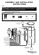
Mounting Screw (B) Wire Connector (C) Long Set Screw (D) Short Set Screw (E)Mounting Plate Unit (A)
1. Remove the long set screw (D), short set screw (E) and the mounting plate unit (A) from the backplate.
2. Attach the mounting plate unit (A) to the outlet box by using two mounting screws (B) .
3. Pull out the source wires from the outlet box. Make wire connections using wire connectors (C) as follows:
• Connect the hot wire (usually black insulation) from the fixture to the black wire from the power source.
• Connect the neutral wire (usually white insulation) from the fixture to the white wire from the power source.
• Attach the fixture grounding wire (usually green insulation or bare wire) to the mounting plate unit (A) with the green
grounding screw. Then, depending on local code, connect it to the house grounding wire with the wire connector (C).
Carefully put all of the wires back into the outlet box.
4. Attach the backplate to the mounting plate unit (A) by aligning holes, secure the long set screw (D) from the top
hole of the backplate into the open hole of the mounting plate unit (A). Then secure the short set screw (E) from
the bottom hole of the backplate to the bottom side of the mounting plate unit (A).
NOTE: With silicone caulking compound,caulk complete around the backplate meets with the wall surface
to prevent water from seeping into the outlet box.
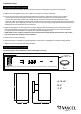
5. Remove the cover from the fixture.
6. Install the bulbs (not included). See relamping label at socket area or packaging for maximum wattage allowed.
7. Attach the cover onto the top of the fixture carefully.
Cover
X1
10204CS
A: 14-1/4"
B: 5"
C: 8"
A
B
C