
Installation Sheet
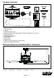
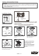
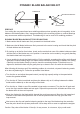

NOTE: Before installing blade
brackets to the motor, please
remove the plastic inserts.
PAGE: 6 / 7
Secure blade brackets to the motor with
motor screws and washers.
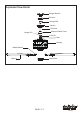
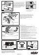
Assembly without fan light
Make sure the lead wire of fan light
in switch box is sealed with a wire
nut exactly. Secure the switch box
cover with the switch box screws.
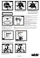
Replace the fan housing inner bulbs
Screw
Plastic Insert
Fig.14
Motor Screw
Blade Bracket
Fig.16Fig.15
Switch Box
Screw
Fig.21
Connect the two terminals respectively
from the motor and the switch box.
Open the inner light plate of worse bulbs
by screw driver.Take off the worse bulb
and install the new one.
Secure the inner light plate back
Switch Box
Screw
Fig.22
F A N C OF A N C O
121203
Fig.19
U / L
D / L
HI
LOW
OFF
MED
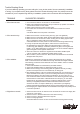
Install the battery (9V, not included) to the transmitter.
Turn on the electric circuit.
Press "HI" button to
operate
the fan in high speed.
Press "MED" button to
operate
the fan in medium
speed.
Press "LOW" button to
operate
the fan in low speed.
Press "OFF " to turn the fan off.
Press and release the "U/L" button quickly to turn
on/off the upper light.
Press and hold the "U/L" button to adjust the
illumination of upper light with the dimmer switch.
Press and release the "D/L" button quickly to turn
on/off the the lower light.
Press and hold the "D/L " button to adjust the
illumination of lower light with the dimmer switch.
Bulb Type B Max.15W
(Included)
Bulb Type B Max.15W
(Included)
Note:
This remote controller has memory function setting. The fan will operate at the same
speed and the fan light will stay at the same status as the last time the power supply
was turned off.
OFF
U/L
D/L
HI
LOW
MED
Fig.18
Turn ON the electric circuit at the
main fuse or circuit breaker box.
The slide switch sets the direction
of fan rotation. Select the direction
of fan rotation you need by sliding
the switch.
Push the slide switch left for
"Forward" and right for "Reverse".
Fig.17
Slide Switch
Reverse
Forward
MED
HI
OFF
U/L
D/L
LOW
Install the transmitter wall bracket in
wall by two screws and hang
transmitter in it carefully. (See Fig.20)
Fig.20
Wall Bracket
Transmitter
Screw
MED
HI
OFF
U/L
D/L
LOW