
Specification Sheet

200716
Turn on the power at fuse or circuit box.
Installation steps
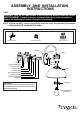
1. Unscrew the two bolt nuts. Remove the two rubber pads and the cross bar unit (A) from the backplate.
2. Attach the cross bar unit (A) to the outlet box using two mounting screws (B). Adjust the length of the preinstalled
headless screws if necessary.
Note: Make sure that the headless screws are lined up horizontally to make the fixture level.
3. Pull out the source wires from the outlet box. Make wire connections using wire connectors (C) as follows:
• Connect the hot wire (usually black insulation) from the fixture to the black wire from the power source.
• Connect the neutral wire (usually white insulation) from the fixture to the white wire from the power source.
• Attach the fixture grounding wire (usually green insulation or bare wire) to the cross bar unit (A) with the
green grounding screw. Then, depending on local code, connect it to the house grounding wire with the wire
connector (C).
Carefully put all of the wires back into the outlet box.
4. Attach the backplate of the fixture to the cross bar unit (A) by aligning and inserting the two headless screws from
the cross bar unit (A) into the open holes on the backplate, then place the two rubber pads over the exposed
headless screws before screwing the two bolt nuts.
Note: With silicone caulking compound, caulk completely around where the backplate meets with the wall
surface to prevent water from seeping into the outlet box.
5. Attach the shade onto the fixture, secure it with the socket ring.
6. Install bulb (not included). See relamping label at socket area or packaging for maximum wattage allowed .
Turn off the power at fuse or circuit box.
Turn on the power at fuse or circuit box.
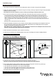
1. Turn off the power at the fuse or circuit box before starting installation.
2. Loosen the wire connector connected with the wires from photocell. (See Fig.1)
Note: Do not move the photocell to prevent water from seeping into the outlet box.
3. Take a white pigtail and black pigtail and make wire connections using wire connector (C): (See Fig.2)
a. The black wire from the fixture to one end of the black pigtail.
b. The white wire from the fixture to one end of the white pigtail.
c. The other end of the black pigtail to the black wire from the power source.
d. The other end of the white pigtail to the white wire from the power source.
Put all wires back into the back plate of the fixture.
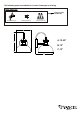
Operation the Unit Without Photocell
Photocell
White Wires From Photocell
Wires From Fixture
Wires From Fixture
Wires From
Main Power
Wire Connector (C)
White Pigtail
Pigtail
Red Wires From Photocell
Black Wires From Photocell
Fig.1
Fig.2
Wire Connector