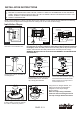
Model No.
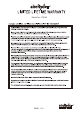
Package Contents: 3 2 7 6 5 4 8 9 9V 10 X10 11 Installation Instruction 1 12 13 Unpack your fan and check the contents. You should have the following items. 1.) Hanger Bracket 2.) Canopy 3.) Decorative Cap 4.) Downrod Stand Cover 5.) Downrod Set (Included Hanger Ball, 6” Downrod, Hanger Pin & Lock Pin) 6.) Fan Motor Assembly 7.) Fan Blades (3PCS) 8.) Blade Holder (3PCS) 9.) Fan Light Kit 10.) Remote Control Set (Includes Transmitter & Receiver & Wire Connectors & Battery ) 11.
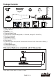
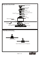
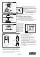
Exploded View Detail Hanger Bracket Hanger Ball Downrod Canopy Decorative Cap Downrod Stand Cover Hanger Pin Lock Pin Collar Housing Blade Holder Blade Switch Box Switch Box Screw Fan Light Dual Mount Drawing Downrod Mount Slope Ceiling Mount (Up to 23 degrees) PAGE: 3 / 9 181128
Safety Instructions READ ALL SAFETY INFORMATION AND INSTALLATION INSTRUCTIONS BEFORE YOU BEGIN TO INSTALL THE FAN AND SAVE INSTRUCTIONS. All set screws of the fan must be checked and retightened where necessary before installation. To reduce the risk of personal injury, do not bend the blade brackets when installing the brackets, balancing the blades or cleaning the fan. Do not insert foreign objects between rotating fan blades.
INSTALLATION INSTRUCTIONS IMPORTANT: BEFORE YOU BEGIN INSTALLING THE FAN, CAREFULLY READ ALL INFORMATION ON THE SEPARATE SHEET "SAFETY INSTRUCTIONS" AS WELL AS THE FOLLOWING "INSTALLATION INSTRUCTIONS". IF IN DOUBT, CONSULT A QUALIFIED ELECTRICIAN. SAVE ALL INSTRUCTIONS. NOTE: The fan weight is 17.28 lbs (7.84 kgs). Be sure the outlet box you are using is securely attached to the building structure and can support the full weight of the fan. Failing to do so can result in serious injury.
Antenna Receiver There is a code switch in the transmitter and receiver. This "DIP Switch" is a 4 key units (Fig.8). All keys were set at "ON" position in the beginning. Set the keys to a different code. Make sure the same numbered keys are switched "ON" for both DIP switches (Fig.8a). If the remote controlled fans are installed than one or the frequency is interfered, the fan may function abnormally. DIP Switch Fig. 8 Fig.8a Code example: 1-ON 2-OFF 3-ON 4-OFF on both DIP Switches.
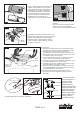
Fig.13a Motor Align holes and fasten blade holder to the motor with screws.Then align holes and fasten blade to the blade holder with blade screws.Repeat for remaining blades and blade holders (Fig.12a). Suggest: Using magnetic Philips screwdriver. NOTE: The blade outside edge angle and blade holder outside edge angle must be same(Fig.12b). Blade Holder Screw Blade Holder Edge Angle Motor Blade Screw Blade Angle Edge Fig.13b Fan Blade Fig.
Trouble Shooting Guide If you have difficulty operating your new ceiling fan, it may be the result of incorrect assembly, installation or wiring. If you experience any faults, please check this Trouble Shooting Guide. If a problem cannot be remedied or you are experiencing difficulty in installation, please call our Customer Service Department (1-800-887-6326). PROBLEM SUGGESTED REMEDY 1. If fan does not start: 1. Check main and branch circuit fuses or circuit breakers. 2.
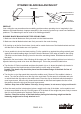
DYNAMIC BLADE BALANCING KIT YARDSTICK 1 BALANCING WEIGHT CENTERLINE 2 3 4 5 6 7 8 MEASURING POINT 9 PLASTIC CLIP COUNTERCLOCKWISE PREFACE Your ceiling fan may sometimes have wobbling problems when operating due to irregularity in the blades or the blade brackets. Improper assembly in the mounting system may cause some additional problems. This balancing kit can be used to fix wobbling problems. DYNAMIC BLADE BALANCING KIT FOR CEILING FANS 1.