VB4000-5000-6000 Series Network Video Appliances VBrick v4.
Copyright © 2007 VBrick Systems, Inc. All rights reserved. 12 Beaumont Road Wallingford, Connecticut 06492, USA www.VBrick.com This publication contains confidential, proprietary, and trade secret information. No part of this document may be copied, photocopied, reproduced, translated, or reduced to any machine-readable or electronic format without prior written permission from VBrick.
Contents MPEG-2 Admin Guide Organization . . . . . . . . . . . . . . . . . . . . . . . . . . . . . . . . . . . . . . . . . . . . . . . . . . . . . . . . . . . . . ix Getting Help . . . . . . . . . . . . . . . . . . . . . . . . . . . . . . . . . . . . . . . . . . . . . . . . . . . . . . . . . . . . . ix Font Conventions . . . . . . . . . . . . . . . . . . . . . . . . . . . . . . . . . . . . . . . . . . . . . . . . . . . . . . . . . . x Printer-Friendly . . . . . . . . . . . . . . . . . . . . . . . . . . . .
Configuration: Conferencing . . . . . . . . . . . . . . . . . . . . . . . . . . . . . . . . . . . . . . . . . . . . . . . . . 37 Configuration: Passthrough . . . . . . . . . . . . . . . . . . . . . . . . . . . . . . . . . . . . . . . . . . . . . . . . . . 39 Configuration: Passthrough > COM1 . . . . . . . . . . . . . . . . . . . . . . . . . . . . . . . . . . . . . . . 39 Configuration: Passthrough > COM2 . . . . . . . . . . . . . . . . . . . . . . . . . . . . . . . . . . . . . . . 43 Configuration: System .
. Diagnostics Overview . . . . . . . . . . . . . . . . . . . . . . . . . . . . . . . . . . . . . . . . . . . . . . . . . . . . . . . . . . . . . . . . 79 User Diagnostics . . . . . . . . . . . . . . . . . . . . . . . . . . . . . . . . . . . . . . . . . . . . . . . . . . . . . . . 79 Diagnostics: Network Tests . . . . . . . . . . . . . . . . . . . . . . . . . . . . . . . . . . . . . . . . . . . . . . . . . . 79 Diagnostics: Network Tests > Ping Test. . . . . . . . . . . . . . . . . . . . . . . . . . . . . .
Configuration: FTP File Transfer > Transfers . . . . . . . . . . . . . . . . . . . . . . . . . . . . . . . 113 VBStar Status . . . . . . . . . . . . . . . . . . . . . . . . . . . . . . . . . . . . . . . . . . . . . . . . . . . . . . . . . . . .
MPEG-2 Admin Guide This VBrick MPEG-2 Admin Guide is written for anyone who will be using or configuring a VB6000 Series MPEG-2 VBrick appliance. This includes system administrators, network technicians, and anyone who will be using or configuring a VBrick network video appliance. VBrick encoder and decoder appliances are available in industry standard MPEG-2, MPEG4, and other formats. MPEG-2 appliances are used for delivering low delay, DVD quality video over high bandwidth networks.
If you can't find the information you need from the online help, or from your certified VBrick reseller, you can contact VBrick Support Services on the web. Support Services can usually answer your technical questions in 24 business hours or less. Also note that our publications team is committed to accurate and reliable documentation and we appreciate your feedback. If you find errors or omissions in any of our documents, please send e-mail to documentation@vbrick.com and let us know.
Chapter 1 Introduction Topics in this chapter Overview . . . . . . . . . . . . . . . . . . . . . . . . . . . . . . . . . . . . . . . . . . . . . . . . . . . . . . . . . . . . . . . . . 1 VBSSM . . . . . . . . . . . . . . . . . . . . . . . . . . . . . . . . . . . . . . . . . . . . . . . . . . . . . . . . . . . . . . . . . . . 1 Mixed Model Appliances . . . . . . . . . . . . . . . . . . . . . . . . . . . . . . . . . . . . . . . . . . . . . . . . . . . . .
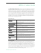
• • • • • Video encoding rates configurable from 8 Kbps to 15 Mbps. Transport and Elementary stream support. Provides closed captioning with text insertion. Optional – video camera with pan, tilt and zoom. Optional – 19 in. rack mount adapter (holds two across). Table 1. VBSSM Models † Model Configuration Description 9170-4200-000x VBSSM-MP2 Ruggedized single channel MPEG-2 encoder. 9171-4200-000x VBSSM-MP4 Ruggedized single channel MPEG-4 encoder with audio. Same enclosure as VBSSM-MP2.
Introduction Figure 1.
4 © 2007 VBrick Systems, Inc.
Chapter 2 MPEG-2 Configuration Topics in this chapter MPEG-2 Overview . . . . . . . . . . . . . . . . . . . . . . . . . . . . . . . . . . . . . . . . . . . . . . . . . . . . . . . . . 5 Configuration: Network . . . . . . . . . . . . . . . . . . . . . . . . . . . . . . . . . . . . . . . . . . . . . . . . . . . . . . 9 Configuration: Billboard . . . . . . . . . . . . . . . . . . . . . . . . . . . . . . . . . . . . . . . . . . . . . . . . . . . . 14 Configuration: Decoder . . . . . . . . . . . . . . . . . . .
Table 2. IWS Configurable Options Option Applicable Model Network All VBrick models. • Ethernet. Billboard Only on models which have decoders. Decoder Single or dual: • Ethernet MPEG-2. • Ethernet MPEG-4. • SDI MPEG-2 (see SDI Configuration). Encoder Single or dual: • Ethernet MPEG-2. • SDI MPEG-2 (see SDI Configuration). • Text insertion. Pump VBStar models only (see VBStar). Recorder VBStar models only (see VBStar). FTP File Transfer VBStar models only (see VBStar).
MPEG-2 Configuration original content and signal, and the quality of the decoder and monitor. As a general rule, use the lowest video rate that best suits the application. The following information represents guidelines for product configuration limitations, with regard to specific unit types. When configuring VBrick units, close attention must be paid to the total transport rate of all sources both entering and exiting the unit.
Model Dest1, Dest2 Slot #1 Decoder Slot#2 Recorder FTP Active Player / Pump 6200 15,15 15 0 No 0 6200 13,0 13 13 No 0 6200 12,0 12 12 Yes 0 6200 11,0 11 0 No 11 6200 9,0 9 0 Yes 9 6200 11,11 11 11 No 0 6200 10,10 10 0 No 10 4300 17,0 17,0 0 No 0 4300 11,11 11,11 0 No 0 4300 13,0 13,0 13 No 0 4300 11,0 11,0 0 No 11 4300 9,9 9,9 9 No 0 4300 8,8 8,8 0 No 8 5300 17 17 0 No 0 5300 13 13 13 No 0 5300 14 14 0 No 14
MPEG-2 Configuration Configuration: Network Configuration: Network > Ethernet Network DHCP Dynamic Host Configuration Protocol – (Enable, Disable). On Ethernet models, if DHCP is enabled, the VBrick gets its IP Address or Network Timer Server and Subnet Mask from the DHCP server. If the DHCP server supplies the Gateway Address or DNS server address, these parameters will replace the user entered Gateway and DNS Time Server settings.
Gateway IP Address Valid gateway IP Address for communicating across distinct network segments. A valid gateway IP address is essential even though the VBrick will operate without one in some cases. When no gateway is configured, the VBrick may be unable to communicate with off-net IP hosts, for example, a foreign host which is used for configuration management via IWS.
MPEG-2 Configuration Maximum Transmission Unit Size Range 1024–1500 (default = 1500). The MTU is used for all network traffic from the VBrick and defines the largest network packet size that will be transmitted. A higher MTU brings higher bandwidth efficiency and VBrick recommends using the default. However you may wish to reduce MTU size to meet the requirements of some networks with VPN or other security tunnels that cannot tolerate 1500-byte packets.
12 Routing Method This selects which routing method will be used: Changes made to the Routing Method will require a reset of the box. • Static – Allows routes entered in the static routing table to be automatically applied to the internal routing tables, after a powerup. • RIP Version 1 – Configures the VBrick to listen to RIP announcements. Routes are dynamically added per RIP specification. • RIP Version 2 Broadcast – Configures the VBrick to listen to RIP version 2 announcements.
MPEG-2 Configuration Configuration: Network > Management These parameters define information used in the SAPs emitted by the VBrick, which are received by the VBDirectory management tool (see the VBDirectory User Guide) and other VBrick applications such as the ETV Portal Server. Group Name Optional. This parameter defines the Group Name. It is included in the Management SAPs used by VBDirectory. It is used for organizing VBricks into groups to simplify use of VBDirectory. Unit Number Optional.
Configuration: Network > IPv6 In the current implementation of IPv6, MPEG-2 encoded streams can be unicast over IPv6 to an IPv6-enabled version of VBrick StreamPlayer. In this version, you continue to manage and configure the appliance over IPv4. IPv6 Auto Config Enable Enable IPv6. When enabled, the IPv6 parameters for IP Address and Gateway IP Address are automatically set. This is the recommended method. IP Address IPv6 IP address of the VBrick.
MPEG-2 Configuration On/Off Turn Billboard on or off. IR Enable the IR remote control. If enabled you can turn the Billboard on or off using the remote. URL The local or external URL of the Billboard page. Using the Billboard Billboard may be invoked in several ways. Either use the PC browser to communicate with the VBrick Integrated Web Server (see separate section) to apply the billboard and turn it on and off, or press the Billboard key on the optional remote control to toggle it on and off.
Use the Username and Password (default is case sensitive admin, admin) to login to the VBrick. BB01 through BB16 are directories established to receive Billboard content. It is possible to cut and paste new contents to a Billboard location from a file located anyplace on the network or on the computer. To view the contents on the VBrick, change the URL in the Billboard Section of the Integrated Web Server. In this example, the URL for the new file in IWS Configuration: Billboard would read: file://.
MPEG-2 Configuration Creating a Billboard A billboard that fits on one screen (640 x 480 resolution) can be created using the following HTML tags: A DIR H3 IMG PRE AREA DL H4 INPUT SCRIPT B DT H5 LI SELECT BASE EM H6 MAP SMALL BIG FONT HR MENU STRONG BLOCKQUOTE FORM HTML META STYLE BODY TH TITLE NOBR NOFRAMES TABLE BR FRAME FRAMESET CAPTION HEAD TR OL TEXTAREA CENTER H1 U OPTION UL DD H2 I P TD The billboard text generated by the browser is Times Roman.
Configuration: Decoder Configuration: Decoder > Video The VBrick decoder is used to uncompress MPEG streams and display them on a TV or monitor. 18 Decoder Video Format The format can be configured to be NTSC (30fps), PAL (25fps) or PAL-M (30fps). PAL-M is a video format standard used in Brazil. The main difference between PAL and PAL M is a lower resolution (525 lines instead of 625) and a higher frame count (30 frames per second at 60Hz versus 25 frames per second at 50Hz).
MPEG-2 Configuration Actual PID Actual PID being played. This read-only parameter is of interest when the user selects automatic. A value of 8191 indicates the PID has not yet been established. Configuration: Decoder > Audio The audio selection provides for the control and configuration of the decoded audio stream. Output Mode The audio output mode can be one of five possible setting as shown below.
Right Gain Used to adjust volume. Default = 0. Configure PID MPEG-2 transmits its data in packets of 188 bytes each. At the start of each packet is a packet identifier (or PID) identifies the data stream associated with that packet. Because the MPEG-2 data stream might contain multiple audio programs, the decoder has to choose a particular audio channel to play. The PID selection provides that feature.
MPEG-2 Configuration Receive Address Mode Allows the user to specify how the receive address will be configured: IP address, Host Name, or Program Name. If Program Name, select from the dropdown list of Available Programs. Available Programs Select from dropdown list of available programs. This automatically populates Receive IP Address and Source IP Address. Receive Host Name Sets the source for video by using the Host Name. This parameter can be used only for a unicast source.
SAP Timeout If SAP Timing method is fixed, this provides a configurable timeout for program guide selections, in seconds. If no SAP is received within the timeout period, the entry is removed from the table of available programs. If SAP Timeout is variable, the entries are removed from the program table as per RFC 2974 (Refer to Configuration: System > General).
MPEG-2 Configuration Picture in Picture By checking the Box this will enable the Picture-In-Picture display. PIP Location Picture-In-Picture can be any of the following 5 locations: top left, top right, bottom left, bottom right and center. PIP Horizontal Size The Picture-In-Picture horizontal size can be changed to any of the following 4 sizes – full, half, quarter, thumbnail.
Configuration: Encoder Configuration: Encoder > Transport Transport Rate This option allows selection of the actual transport rate for the MPEG-2 transport stream transmitted from this encoder. If Auto is selected, the VBrick will choose an appropriate conservative transport rate, which will allow any video interval to be clearly transmitted. If you enter a rate that is less than the combined video, audio and over-head an error message will be displayed indicating that the rate selected is too low.
MPEG-2 Configuration Audio PID MPEG-2 transmits its data in packets of 188 bytes each. At the start of each packet is a packet identifier (or PID) that identifies the data stream associated with that packet. It is possible that a non-VBrick decoder may only accept audio streams with a certain PID setting. If so, then this feature allows compatibility with these decoders. Video PID MPEG-2 transmits its data in packets of 188 bytes each.
Video Format The format can be configured to be NTSC (30fps), PAL (25fps) or PAL-M (30fps). (The PAL-M feature is supported on models ending in xxx1 or higher.) PAL-M is a video format standard used in Brazil. The main difference between PAL and PAL-M is a lower resolution (525 lines versus 625) and a higher frame count (30 frames per second at 60 Hz versus 25 frames per second at 50 Hz). Video Aspect Ratio Aspect ratio is the ratio of the width of the image to the height of the image.
MPEG-2 Configuration Closed Caption Enable Disables or enables closed captioning. It is recommended that Closed Caption be disabled unless required by an application. Default = disabled. Does not apply to models ending in -xxx0. • Disabled – Default. • Video CC Enabled – Reads the embedded video closed captioning text. • Inserted CC Enabled – Inserts the user defined text set in the Closed Caption Text field. Closed Caption Type Sets the Closed Caption Type to either ATSC Compliant or Alternate Format.
Reference Distance For models ending in -xxx1/-xxx2, enables a user to set the difference between consecutive reference frames within a group of pictures (GOP). The values available are 1–3 (default = 2). If the Encoder Transport Delay setting is low or medium, the value must be 1. Does not apply to models ending in -xxx0. If Reference Distance and Intrapicture Distance are both 1, the encoder will produce all I frames.
MPEG-2 Configuration Video GOP Time The hours, minutes and seconds for the GOP time, the creation time of the MPEG video stream. Can be set to one of three selections: • Encoder Time (default) • GMT Time • Local Time Note: Within the GOP header of the video stream is a Time Stamp, in hours, minutes and seconds. If the receiving application uses this time stamp, it is desirable to configure the encoder to insert a real time of day in either local or GMT time.
30 Audio Input Input can be from an Audio Jack (1/8" mini-phono jack) or from Microphone DIN (AudioMate microphone). The default setting is Audio Jack. Audio Balance -127 to 127. Sets audio balance between left and right channels. Zero is balanced. 127 sends audio to right channel only; -127 to left channel. Audio Input Level Hardware-dependent; not shown on all models. See Audio Gain field for more details. • Normal – 7 to –53 dB and mute. • Alternate – 12 to –48 dB and mute.
MPEG-2 Configuration Audio Channels Model dependent. (If the EEPROM Revision is 2 or higher, changing the Audio Channel setting affects the Sample Frequency. ) • If the model number ends in –xxx0, the parameter can be set to Stereo, Mono and Dual. The default setting is Stereo. • If the model number ends in –xxx1/-xxx2, the settings are dependent on the PLX EEProm revision Number: • If the EEProm Revision is 1, this parameter can be set to Stereo and Mute. The default setting is Stereo.
Destination Address Mode Allows the user to specify how the destination address will be configured: IP Address, Host Name, or IPv6. • IP Address – This is the Destination IP Address of the encoded video. When this is a multicast address, the transmit mode is also set to multicast. Similarly, if this is a unicast address, the transmit mode is also set to unicast. • Host Name – Sets the source for video to be received using Host Name of the source. It can be used only for a unicast source.
MPEG-2 Configuration Unicast Ping Feature for primary destination can be enabled, disabled. If the VBrick is designated to transmit a transport stream to any destination (whether another VBrick or not) in unicast mode, this parameter is used to instruct the VBrick to ping the destination periodically to test connectivity before sending the stream. If Unicast Ping is not enabled, and the destination goes off-line, the unicast stream may be broadcast to all destinations causing flooding on the network.
Announce Common Information 34 Program Name The string providing the name of the stream associated with this SAP. This SAP text shows up in the Program Guide for other VBrick products. Default is \H Program x (where x is 1 or 2, for slot1 or slot2). Note: All of the Common Information fields support replacement characters. The replacement text is only shown in the SAP message at the destination decoder. The fields are replaced by the actual information as explained below.
MPEG-2 Configuration Category An encoder can have a SAP Category string. This string consists of one or more keywords separated by spaces. Each category keyword represents a tag associated with the Encoder's video stream. Decoders can be configured to display in their Program and Guides only video streams tagged by specific category keywords or those containing no keyword. The string(s), used by the Decoder, is set on the Decoder/Network screen. Note: Characters are ASCII and are case sensitive.
SAP Port The receive IP port used to populate the Program Guide. This is typically the port number of the encoder. Note SAP information appears in the Program Guide field displayed in other VBrick products, such as StreamPlayer and StreamPlayer Plus. Configuration: Encoder > Text Insertion The Text Insertion feature is a hardware option for MPEG-2 encoders and requires a separate daughter card. It lets you configure text messages that overlay the video stream during encoding.
MPEG-2 Configuration User String 36 characters maximum. This is the actual text message that will be displayed and refreshed at the interval specified above. You can use any combination of alphanumeric and special characters. The following standard operators are supported in the text message. • \s1 – Blinking on. • \s0 – Blinking off. • \h – The VBrick Host Name on Configuration: Network page. • \t – The time in HH:MM:SS format. • \d – The date in MM:DD:YY format.
38 Conferencing Setup This option enables/disables the ability of a user to initiate a conference using an IR remote control unit. Disabled prevents this VBrick from appearing on the Conference Guide of other VBricks. Conferencing Accept If Manual , the called party on this VBrick must explicitly accept the call with the IR remote control. If automatic, the call will be accepted without any action on the part of the called party. Local Ringer Used to enable/disable the ringer.
MPEG-2 Configuration Configuration: Passthrough The TCP/IP network can serve as an intermediary between two VBricks and their serial ports or between a PC application sending IP packets and a VBrick's serial port. Passthrough can be configured using addresses on Ethernet. Passthrough on COM2 is only available on VBricks with a CPLD (programmable logic device) Version greater than 21. (To check the CPLD , go to Status > System Information > CPLD Version .
Operational State Describes the current status of a Passthrough connection, including error conditions, if any. Refer to the Network Status Section. This will display "Active" if in Passthrough mode. COM Interface Type Describes the COM interface connector. (RS422/485 options are displayed only if main board has a Part Number ending in xxx3. See Status: User Information > Main Board.) • RS232 – standard RS-232 serial port connector. • RS422/485 – RS-422/485 4-wire serial port connector.
MPEG-2 Configuration COM Interface Type Describes the COM interface connector. (RS422/485 options are displayed only if main board has a Part Number ending in xxx3. See Status: User Information > Main Board.) • RS232 – standard RS-232 serial port connector. • RS422/485 – RS-422/485 4-wire serial port connector. • RS422/485 (Terminated) – RS-422/485 terminated.
Destination • Remote COM1 using Slot1 Video Endpoint. This means that all serial data originating at the COM1 port being configured is sent to the COM1 port of the VBrick identified as the Slot1 video source (if Slot1 is a decoder) or to the Slot1 video destination VBrick (if Slot1 is an encoder). • Remote COM2 using Slot1 Video Endpoint. Slot1 Destination 1 only. Same as above except Initiator destination is COM2. • Dedicated.
MPEG-2 Configuration Operational State Describes the current status of a Passthrough connection, including error conditions, if any. Refer to the Network Status Section. This will display Active if in Passthrough mode. Idle Time out 5–2000 milliseconds. Default = 500. The interval between characters at which metadata is inserted into the stream. COM Interface Type Describes the COM interface connector. (RS422/485 options are displayed only if main board has a Part Number ending in xxx3.
Configuration: System > General Network Time Synchronization Enabled or Disabled. If enabled, the System Date Time field is inactive. See Network Time Synchronization on page 11 to set host name or IP address of time server. You must set these parameters before you can enable Network Time Synchronization on this window. System Date Time Set system date and time in mm/dd/yyyy hh:mm format. System 44 Current Operational Mode Indicates the current operational mode of the VBrick.
MPEG-2 Configuration Time Zone Select from list: (GMT-12) Eniwetok – (GMT +12) Auckland. Daylight Savings Time Enabled or Disabled. IR Enable Enable or Disable the IR remote control. This is the master enable and disable for the IR across all functions. Fan Mode This option allows a user to either force the fan always high or to automatically cycle on and off based on measured temperature. Default = Automatic.
manager application (not supplied). The SNMP MIB, which formally defines the SNMP interface to the VBrick, is contained within the install directory of the VBrick release or from the VBrick. The two MIB files are VBrick_box2.mib and VBrick_reg.mib. The default installation directory is: Program Files\VBrick\VB6000\Download\ReleaseVxx_xx_xx Traps are SNMP base messages used by SNMP elements to report changes in status or alarm conditions to remote SNMP management entities.
MPEG-2 Configuration SNMP Trap Version Select Version number. Trap User Name User assigned trap name. Authentication Password Enter password. Cannot exceed 20 characters. May include any combination of alphanumeric characters but only the following special characters: ~ ! # $ ^ * + & % [ ] { } | < > See Table 5 on page 93 for defaults. Authentication Protocol Select protocol: MD5 or SHA to validate the transaction between a given host and client Privacy Password Required.
48 Number Event Description 22 The 2.5 volts power supply failure has cleared. 23 There is a Real Time Clock battery failure. 24 The unit has been configured to transmit and/or receive video streams beyond its capability. 25 Signifies the overloaded unit is recovered to normal. 26 A component on the main board failed Power On Self Test (POST). 27 The encoder card in Slot1 failed Power On Self Test (POST). 28 The encoder card in Slot1 failed Power On Self Test (POST).
MPEG-2 Configuration Configuration: System > Security Note If you disable Telnet, FTP, IWS, and SNMP, the only way to manage (and re-enable) these parameters is to connect a PC to the VBrick with a serial cable and use the Command Line Interface (CLI). You should never disable all the network management interfaces if you are using COM2 for serial passthrough. External Telnet Server Default = Enabled. Disabled will prevent Telnet sessions to the server. External FTP Server Default = Enabled.
is related to user accounts and passwords. After a successful installation, you should immediately change the default passwords. Many attacks come from within an organization and this helps to minimize the risk. The IWS login is generally secure since it utilizes encryption techniques to hide usernames and passwords from network spyware. Malicious software covertly attaches itself to unsuspecting devices. These programs are generally designed to compromise personal information or to create system havoc.
MPEG-2 Configuration Log Time Zone Specifies the time zone (Local or GMT) that is used for logged events. Trap Log Local If Enabled, displays trap events in the local log. Trap Log Remote If Enabled, sends trap event notices to a remote host. General Config Log Local If Enabled, displays configuration changes in the local log. General Config Log Remote If Enabled, sends configuration change notices to a remote host.
Video On Demand Enables or Disables the Video-on-Demand capability of the VBrick appliance. When enabled, the user will be able to view Video-onDemand SAPs in the Program Guide. If authorized, the user will be able to select Video-on-Demand SAPs and access the Video-onDemand features of the VoD server sending the SAP. If disabled, the user will not see Video-on-Demand SAPs in the Program Guide. SAP IP Address The IP Address for Video-on-Demand SAPs Default value is 224.2.133.135 (as shown).
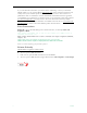
MPEG-2 Configuration Figure 2. Script Management – Part 1 Click here to read Login to the VBrick via FTP and manage script files. Requires a valid or write script files user name and password. Event Enable Allows the user to Enable/Disable Event Triggering for each input event. Event Stable Time Allows the user to enter the amount of time in milliseconds that each input event has to be stable at the active level before the script will be executed.
Figure 3. Script Management – Part 2 Event Count Displays the number of times each input event has occurred. Event Script Status Displays current status information for each event script. Run Script These buttons allow the user to run each script without needing the input event. Use this method to test the script. IR Remote Scripts are enabled by simply placing a file named irNScript.txt (where N is a number from 0–9 ) in the script directory of the unit.
MPEG-2 Configuration Scripting Notes • • • • • • • • • • * denotes end of group. Each group can have a maximum of six sets. Each group must have apply sets for all normal sets. Wait state will be alone in a group. There is no clear command. Script commands must start in column 1. There is no chaining of scripts. Comments will start with / and can be a line or the end of a command. All scripts are executed in a strictly serial manner by a single task.
URL Valid path to a URL script file, for example: www.myserver.com/ config.xml . Default = blank. Poll Rate The rate at which the appliance checks the config file. 0–1440 minutes (default = 0). Auto Config Status Shows auto config status including when the script was last run, URL connection errors, etc. Press Refresh to update. Run Script Edit mode only. Run the script now. Sample Script The auto config script file (config.xml ) is an .xml file with the following syntax.
Chapter 3 SDI Configuration Topics in this chapter Introduction . . . . . . . . . . . . . . . . . . . . . . . . . . . . . . . . . . . . . . . . . . . . . . . . . . . . . . . . . . . . . . 57 Configuration: Encoder . . . . . . . . . . . . . . . . . . . . . . . . . . . . . . . . . . . . . . . . . . . . . . . . . . . . . 58 Configuration: Decoder . . . . . . . . . . . . . . . . . . . . . . . . . . . . . . . . . . . . . . . . . . . . . . . . . . . . .
the SDI output module. The SDI output module is available with model numbers ending in – x110, –x011, -x111, -x010, -x012, –x112. Configuration: Encoder The following sections explain how to configure SDI encoders and decoders. Note that closed captioning is not supported on SDI encoders or decoders. Configuration: Encoder > Video These parameters are used to configure the encoder video settings.
SDI Configuration Configuration: Encoder > Audio The encoder video and audio configurations for an SDI (Serial Digital Interface) equipped appliance are only available on a model ending in part number –xxx1/–xxx2 (see Status: User Information for part number). These parameters are used to set the SDI Encoder Audio Input settings. For SDI equipped units, everything is the same as for the models ending in -xxx1/-xxx2, except for the fields below.
60 © 2007 VBrick Systems, Inc.
Chapter 4 Status The Status menu lets you view information and status relative to the VBrick appliance. The Refresh button allows the user to update the statistics to display the most current values. A Reset button is also present on some screens, allowing a user to reset all statistic counters. Topics in this chapter Status: System Information . . . . . . . . . . . . . . . . . . . . . . . . . . . . . . . . . . . . . . . . . . . . . . . . . . 61 Status: Network Status . . . . . . . . . . . . . . . . . . .
62 System Model Displays the model number of the appliance. MAC Address Displays the MAC (Media Access Control) address of the appliance. MAC Address Valid Verifies that the MAC address is valid. Current Operational Mode Indicates the current operational mode of the VBrick. The following modes are supported: • Run Mode – Normal operation. • Diagnostics – User selected mode for running certain VBrick diagnostics. • Limited Run Mode – Limited operational mode (not selectable).
Status DHCP Status Dynamic Host Configuration Protocol – Ethernet models only. Enabled/Disabled. Possible DHCP Status values: • Disabled • Succeeded • Failed • Succeeded without Subnet Value – No subnet value given; generated from IP address. • Succeeded with Invalid Subnet Value – Invalid subnet value given; generated from IP address. • Failed over Backplane – Device number invalid in backplane. • Failed, Invalid Device Unit – Network interface device number invalid.
General COM1/COM2 Passthrough Operational State The current operational state of COM1/COM2 serial Passthrough port. There will be a conflict if the slot selected through the Passthrough Destination parameter has neither an encoder nor a decoder present; or has an encoder with a multicast destination; or has an encoder with no configured destination.
Status Network Speed Mode The mode of transmission for the Ethernet network interface: Full Duplex or Half Duplex . Interface This section reports the existence of any undesired (and unrequested) video streams being received by the VBrick. Unrequested streams greater than 1.5 Mbps are automatically flagged and dropped. The reporting is made for each IP interface individually. On Ethernet models, only one interface exists.
Network Mask Defines the destination network's address scope specified in the first column. Mask bits which are zeros, identify the host portion of the address space. Bits that are "ones" identify the network portion. Status: Network Status > Network Time Status: Network Status > IPv6 Status: Decoder Status MPEG-2 Decoder Status This menu lets you view vital Decoder statistics. As you Refresh , the Source IP Address and Bytes Transferred fields are updated.
Status Decoder State • • • • • • • • • • • • • • • • • • • • • Displays decoder state from the decoder standpoint.
Source IP Address The IP Address of the video source. Bytes Transferred The number of receive bytes transferred. Buffer Full Count The number of times the decoder buffer filled to capacity. Decoder Sync State Indicates whether the MPEG-2 transport layer has achieved its synchronization. Most likely indicates a configuration or network problem. Lost Sync Count The number of times the decoder has acquired synchronization with the transport stream (see note under Unexpected Fragments).
Status MPEG-2 Encoder Status Encoder State Displays encoder state as running or not running. Micro-Code Revision Displays the encoder micro-code revision. FPGA Revision Displays the FPGA revision number. PLX EEProm Revision Displays the EEProm revision number. Transmit State Displays Transmitting or Not Transmitting. IP Bytes Transferred Number of bytes sent across the network Buffer Full Count Displays any full buffer counts that occur.
Status: Hard Drive Status > General 70 Disk Type This variable contains the Hard Drive model number as reported by the hard drive firmware. Free Space Amount of remaining space on the hard drive. Video File Count Number of files on the hard drive. Read Errors The count of reported block read failures. Write Errors The count of reported block write failures. Open Errors The count of reported file open failures.
Status Status: Hard Drive Status > Pump General Pump State Stopped Running Fast Forward Fast Fast Forward Slow Paused Rewind Fast Rewind Slow Hard Drive Failed No Batch File Pump Bit Rate The bit rate, in bits per second, of the stream being pumped. Pump Duration The duration, in seconds, of the stream being pumped. Current File Name of the file currently being transferred.
Status: Hard Drive Status > Recorder Recorder State Failed Stopped, never started Stopped, by user Stopped, Disk Full Stopped, File Size Limit Stopped, FTP Overrun Stopped, Duration Complete IP Packets Received The number of IP Packets received. Bytes Transferred The number of received bytes transferred across the internal bus.
Status Detected Transport Rate The measured transport rate received by the recorder. File Start Time Allows viewing the start date/timestamp for current or most recent file. Data Recorded Bytes. Current file size of the file being recorded set to “0” if recording is not in progress. File in Progress Name of the file currently being recorded. Last Completed File Name of the last file recorded.
Status: System Log > System Event The system event log contains reports of system events within the VBrick. These events may occur during normal operation and include reports of successful and unsuccessful attempts to access video sources by the local decoder and access to the local encoder using RTSP. Status: System Log > Traps This log contains all of the SNMP traps generated by the box whether or not the traps have been emitted. 74 © 2007 VBrick Systems, Inc.
Status Status: System Log > System Info This log contains unexpected behaviors detected by the VBrick software. Normally this log is used by VBrick Customer Support to help debug possible system malfunctions. Status: User Information Status: User Information > Main Board This menu allows the user to view factory set information regarding the main board.
User Information Version As displayed. Part Number As displayed. Box Serial Number As displayed. Customer Class As displayed if any. Manufacturing Date As displayed. Board Assembly Number As displayed if any. Hard Drive Assembly Number As displayed if any. Board Serial Number As displayed. MAC Address As displayed. Status: User Information > Slot1/Slot2 This menu allows the user to view factory set information relative to the slots in the appliance. 76 © 2007 VBrick Systems, Inc.
Status User Information Version As displayed. Board Assembly Number As displayed. Lot Number As displayed if any. Main Board Serial Number As displayed. This Board Serial Number As displayed.
78 © 2007 VBrick Systems, Inc.
Chapter 5 Diagnostics Topics in this chapter Overview . . . . . . . . . . . . . . . . . . . . . . . . . . . . . . . . . . . . . . . . . . . . . . . . . . . . . . . . . . . . . . . . 79 Diagnostics: Network Tests . . . . . . . . . . . . . . . . . . . . . . . . . . . . . . . . . . . . . . . . . . . . . . . . . . 79 Diagnostics: Device Test . . . . . . . . . . . . . . . . . . . . . . . . . . . . . . . . . . . . . . . . . . . . . . . . . . . . 83 Diagnostics: Decoder Color Bars . . . . . . . . . . . . . . . .
in the top portion of the screen. If the test is interrupted by pressing the Stop button, the results of the test prior to termination will be displayed. Address Mode Select IP Address or Host Name and enter a corresponding value. Number of Packets Number of packets to send for the test (default = 4). PDU Protocol Description Unit size of packets, in bytes (default = 64). Transmit Interval In seconds (default is sending the packets in 1 second intervals).
Diagnostics Operational State The currently selected test. Address Mode Select IP Address or Host Name and enter a corresponding value. IP Address or Host Name Enter the information in the corresponding box. Probe Count Can be set from 3 to 20. The default setting is 3. This setting is the number of probe packets sent to a host at each hop. Trace Route Test Results The results of the test appear at the top of the screen. The results include the Resolved IP Address of the Destination Host Name.
Diagnostics: Network Tests > Data Test Data tests are used primarily to test the integrity of a network connection between two VBricks. A loopback test takes all data received at the video IP port and retransmits the data to the configured transmit IP destination. A loopback test may be used to observe the quality of the video data after looping back at the destination. A loopback test is available only for encoder-decoder models and is bi-directional.
Diagnostics Cell test is available for encoder-decoder, encoder only, and decoder only appliances. In this mode the encoder VBrick transmits the data pattern and the decoder VBrick receives and validates the data pattern. In this mode the following steps are recommended. No timed or continuous option is available for this test mode.
Diagnostics: Decoder Color Bars The Decoder Color Bar test is a simple test that generates color bars at the video decoder and outputs them in the place of video. It can be used to test basic decoder operation and the monitor. 84 © 2007 VBrick Systems, Inc.
Diagnostics Diagnostics: Hard Drive VBrick MPEG-2 Appliance Admin Guide 85
86 © 2007 VBrick Systems, Inc.
Chapter 6 Maintenance Topics in this chapter Maintenance: Device Information . . . . . . . . . . . . . . . . . . . . . . . . . . . . . . . . . . . . . . . . . . . . . 87 Maintenance: Default All Configuration . . . . . . . . . . . . . . . . . . . . . . . . . . . . . . . . . . . . . . . . 88 Maintenance: Read/Write Configuration . . . . . . . . . . . . . . . . . . . . . . . . . . . . . . . . . . . . . . . . 88 Maintenance: Change Usernames & Passwords . . . . . . . . . . . . . . . . . . . . . . . . . . . .
Total System Up Time Displays the total time that the unit has been powered up. Note The Device Information table creates a date and time stamp for every power or reset event. When SNTP is enabled, the unit must reboot to synchronize time with the SNTP server time. If the time moves dramatically forward (or backward), a discontinuity may appear in the device table because of the SNTP time correction.
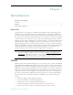
Maintenance Read Configuration Data from Device You can read the configuration parameters from the VBrick by clicking the Read button on the page. After clicking on the button, an xml document with all the configuration parameters will pop up (see Figure 4). The .xml document can then be saved to your PC as an .xml file using File > Save As. To view this file offline, you must download the style sheet (see click here on the screen) to the same directory as the saved file.
Figure 4. Sample VBrick Configuration File Maintenance: Read/Write > Write To Device This page lets you write configuration parameters from an .xml file to the VBrick. On a successful write, all parameters will be saved to Flash and the appliance will reboot. Only administrator level users and above have Write privileges. Note The VBrick appliance that the configuration file is read from, and VBrick appliance that the configuration file is written to must be running the same version of code.
Maintenance Write Configuration Data to Device T To write configuration parameters to the VBrick from an .xml file: 1. Click the Browse button and navigate to the configuration file you want to write to the appliance. Click on the Write button to write the selected file to the VBrick. The configuration parameters will be saved to Flash memory and the appliance will reboot. In the event of a validation error, a message will appear on the screen.
92 User Name Enter desired user name. Cannot exceed 20 characters. It may include any combination of alphanumeric characters and only the following special characters: ~ ! # $ ^ * + & % [ ] { } | < > Password Enter desired password. Cannot exceed 20 characters. It may include any combination of alphanumeric characters and only the following special characters: ~ ! # $ ^ * + & % [ ] { } | < > Confirm Confirm new password entry. Note: Appliance will then inform the user and perform a reboot.
Maintenance Table 5. Default User Names and Passwords User Level Default User Name Default Password Authority Administrator admin admin Read, diagnostics, edit, change password, network and routing. Operator operator operator Read, diagnostics, edit. Diagnostics diagnostics diagnostics Read, diagnostics. Public public public Read Maintenance: Usernames & Passwords > Change SNMPv3 Passwords SNMPv3 provides additional security that exceeds that available with SNMPv2.
User Name Read-only. Set user name on previous page. Authentication Password Enter password. Cannot exceed 20 characters. May include any combination of alphanumeric characters but only the following special characters: ~ ! # $ ^ * + & % [ ] { } | < > See Table 5 for defaults. 94 Authentication Protocol Select protocol: MD5 or SHA. Privacy Password Required. Security Level No Authentication, No Privacy (default). No Privacy. Authentication. Authentication and Privacy. © 2007 VBrick Systems, Inc.
Chapter 7 Maintenance Mode Topics in this chapter Overview . . . . . . . . . . . . . . . . . . . . . . . . . . . . . . . . . . . . . . . . . . . . . . . . . . . . . . . . . . . . . . . . 95 Maintenance Mode CLI Operation . . . . . . . . . . . . . . . . . . . . . . . . . . . . . . . . . . . . . . . . . . . . 97 Overview Maintenance Mode is automatically launched when the software on the VBrick does not boot.
DHCP Enable/ Disable If DHCP is enabled the VBrick must get it's IP address and Subnet Mask from the DHCP server. If the DHCP server supplies the Gateway address or DNS server address, these parameters will replace user-entered parameters. IP Address IP address associated with the Ethernet interface of the VBrick. Subnet Mask Subnet mask for the VBrick Ethernet IP address. Gateway IP Address Gateway IP address for communicating across the Ethernet segment attached to the VBrick.
Maintenance Mode • The Telnet and/or Command Line Interface (CLI) prompt after you login is and displays one of t he following codes. VBMaintMode> Code 10 Operating system failed to load or the flash is corrupted. Code 20 Critical system files are missing or corrupted. Code 30 The Hardware Watchdog has failed. Code 50 Invalid Flash parameters found, defaults used. Code 60 Corrupted Bootline, default used.
98 Command Description Entry c nt 6 xxx To edit the IP Host Name. The default is the Media Access Control (MAC) address, a hardware address that uniquely identifies each node of a network. The Host Name can be a maximum of 18 characters; the first character must be a letter and the last character a number. The middle characters can be letters, numbers or hyphens. c nt 2 yy.yy.yy.y y To edit the IP address Where yy.yy.yy.yy is the new IP address. c nt 3 zz.zz.zz.
Chapter 8 VBStar Topics in this chapter Introduction . . . . . . . . . . . . . . . . . . . . . . . . . . . . . . . . . . . . . . . . . . . . . . . . . . . . . . . . . . . . . . 99 VBStar Pump . . . . . . . . . . . . . . . . . . . . . . . . . . . . . . . . . . . . . . . . . . . . . . . . . . . . . . . . . . . . 100 VBStar Record . . . . . . . . . . . . . . . . . . . . . . . . . . . . . . . . . . . . . . . . . . . . . . . . . . . . . . . . . . . 105 VBStar FTP File Transfer . . . . . . . . . . . . . . . . .
screen icon indicates when a recording is in progress. VBStar combines digital television recording, networking and video storage with an MPEG-2 video server in one compact package. VBStar provides efficient, robust and feature-rich MPEG video storage and playback capabilities. Through its record and FTP capability, VBStar eliminates the reliance on broadband networks, including Quality of Service requirements.
VBStar Configuration: Pump > General Click here to examine ... Click on this link to examine hard drive content. You must know the user name and password to login to the FTP server and view content. You can use any FTP client application to access the hard drive using a URL like this: ftp://admin@/D: Be sure to login to the D: drive as shown. Do not modify or store files on the C: drive. The C: drive has limited space and is reserved for VBrick firmware.
Continuous Enable If Once is selected the selected file or batch will play through to completion and stop. If Continuous Repump is selected, the selected file or batch sequence will be continuously played until the stop button is pressed or a different file is selected. When the file or batch has completed playing it wraps to the beginning and plays again. Auto Pump New File Can be enabled or disabled to allow any file to be automatically pumped on FTP reception.
VBStar Configuration: Pump > Announce (SAP) See MPEG-2 Configuration: Encoder > Announce (SAP) on page 33.
Configuration: Pump > Operation This screen shows you the status of your Pump and allows you to manually Start, Stop and Pause the current Pump. Use the Refresh to update the status. 104 © 2007 VBrick Systems, Inc.
VBStar VBStar Record Using Mixed Models MPEG-2 encoders behave differently when mixed models are present in the same enclosure. For example when there is a WM encoder in Slot1 and an MPEG-2 encoder in Slot2, the MPEG-2 recorder becomes an archiver and not a recorder. This section explains in detail how the MPEG-2 encoder works when functioning as a recorder.
test1.mpg; if test1.mpg, test2.mpg and test3.mpg exist, and the Recorder File Name is still set at test.mpg, the new recording will start at test4.mpg. If the Recorder File Name is set at to particular index number, such as test2.mpg, the first file to be recorded will be test2.mpg and the batch recording will increment from that number. Note The maximum batch file size is 4 GB.
VBStar Configuration: Recorder > General Click here to examine ... Opens an Internet Explorer FTP session window. See Configuration: Recorder > Operation on page 110 for more information. Recorder Mode • User Controlled – The user controls when to record files via any of the following methods: IWS, CLI, IR Remote, SDK, or SNMP. • Start Record on Power-up – When the appliance is powered up the files will begin being transferred. • Recorder Schedule – Files will be recorded at a scheduled time.
Recorder File Name The root name of the file to be recorded. The VBStar recorder can automatically use current date, current time, and/or host name when it creates a new file. Use this feature by configuring the filename to contain any of the following strings in any order. • >h or >H – Host Name. • >d or >D – Current Date. • >t or >T – Current Time. Recorder Source Defines the source of video for record. When Dedicated is selected as the Recorder source, the Network option screen appears as a selection.
VBStar record mode and the recorder attempts to open a new file that has not been completely transferred, the recorder will stop. The Failure condition is noted in the Recorder Status menu. Configuration: Recorder > Network The Network configuration tab is only displayed if you select Dedicated for Recorder Source on the previous Configuration: Recorder > General page. Receive Address Mode Allows the user to specify how the receive address will be configured: IP address or Host Name.
Packet Ordering Toggles the state IP packet ordering. The identification number in the IP header determines IP packet ordering. Out of order packets are discarded prior to being given to the decoder. Generally, when packet ordering is enabled, the VBrick will store the out of order packets and attempt to reassemble the entire datagram. Some sources of video may not utilize the identification number field in a consistent manner and therefore the packet ordering feature may need to be disabled.
VBStar Recorder State Displays the state of the recorder. Values can be Failed Stopped, never started Stopped, by user Stopped, Disk Full (less than 100 MB remains) Stopped, File Size Limit (approximately 4 GB) Stopped, FTP Overrun Stopped, Duration Complete Stopped, Unformatted Stopped, IO Error Stopped, File Is Pumping Running, From Power Up Running, Scheduled Running, User Initiated Recorder Mode Reports the Recorder mode, User Controlled, Start Record on Power-up, or Scheduled.
File in Progress Name of the file currently being sent to the FTP destination server(s). • Last Complete FTP File – Name of the last completed file sent via FTP. • Operation Functions Buttons: • Start Recorder – Starts recording selected file (s) to the Hard Drive destination. • Stop Recorder – Stops recording selected file (s). • FTP Auto Send – FTP last recorded file via enabled servers. • Refresh – Refreshes the content of this screen. Last Completed File The name of the last completed file.
VBStar FTP Server 1–8 Name Ftpserver1 through Ftpserver8. Type VBrick or Non-VBrick Appliance. • VBrick Appliance – When sending to a VBrick appliance, the serving VBrick must select the D: directory. The configuration of VBrick Appliance automatically adds D: to the path name or to any other configured folder or as part of the Directory entry. If no folder is specified, all files will be transferred to the D: directory. Additionally, subfolders may be specified.
FTP Status 114 Current File The filename of the current file being FTPed. Destination FTP server name from server configuration page. State The current state of the Hard Drive. Values can be: • Transfer in Progress • Idle • Invalid FTP Server • Invalid User Name • Invalid User Password • Local File Open Error • Socket Open Failure • Transfer Failure • Socket Quit Failure Size Size of the file to be sent. Rate Transmitted data rate of the file being FTPed. Transfer Current amount transferred.
VBStar Last Queue Operation File added OK; or File removed OK; or blank. FTP Queue Operation Changes to the entries on the screen d not take effect until you select an action button (Add to FTP Queue , Remove from FTP Queue or Flush Queue ). Directory The target directory located on the server. See notes under sending to VBrick and non-VBrick appliances in the previous IWS screen. File Name of the File from the hard drive. Batch The batch filename of an individually indexed batch file.
116 © 2007 VBrick Systems, Inc.
Index A Absolute Maximum Transport Rates 7 Announce Common Information 34 Archiver and Recorder Functionality 2 Hard Drive 85 Network Tests > Ping Test 79 Network Tests > Trace Route Test 80 Domain Name Server 11 B F Billboard FTP 15 Billboard URLs 16 Filename Syntax Rules 105 Font Sizes 17 FTP Queue Operation 115 FTP Server 1–8 113 FTP Server Enable 108 FTP Status 114 C Configuration Billboard 14 Conferencing 37 Decoder 18 Decoder > Audio 19 Decoder > Picture-In-Picture 22 Decoder > Video 18 Decoder
Initiator 41 R Read Configuration Data from Device 89 Recording Batch Files 105 Remote URL 16 S Scripting Notes 55 SDI Configuration 57 Status Decoder Status 66 Encoder Status 68 Hard Drive Status 69 Hard Drive Status > General 70 Hard Drive Status > Pump 71 Hard Drive Status > Recorder 72 Network Status > Codec 63 Network Status > Network Time 66 Network Status > Routing 65 System Information 61 System Log 73 System Log > Config 73 System Log > System Event 74 System Log > System Info 75 System Log > Tra
VBrick Systems, Inc.