VBrick 7000 Series Network Video Appliances VBrick v2.0 H.
Copyright © 2009 VBrick Systems, Inc. All rights reserved. 12 Beaumont Road Wallingford, Connecticut 06492, USA www.VBrick.com This publication contains confidential, proprietary, and trade secret information. No part of this document may be copied, photocopied, reproduced, translated, or reduced to any machine-readable or electronic format without prior written permission from VBrick.
Contents H.264 Admin Guide Preface . . . . . . . . . . . . . . . . . . . . . . . . . . . . . . . . . . . . . . . . . . . . . . . . . . . . . . . . . . . . . . . . . . vii Organization . . . . . . . . . . . . . . . . . . . . . . . . . . . . . . . . . . . . . . . . . . . . . . . . . . . . . . . . . . . . . vii Getting Help . . . . . . . . . . . . . . . . . . . . . . . . . . . . . . . . . . . . . . . . . . . . . . . . . . . . . . . . . . . . . vii Font Conventions . . . . . . . . . . . . . . . . . . . . . . .
Passthrough . . . . . . . . . . . . . . . . . . . . . . . . . . . . . . . . . . . . . . . . . . . . . . . . . . . . . . . . . . . 26 SNMPv3 Passwords . . . . . . . . . . . . . . . . . . . . . . . . . . . . . . . . . . . . . . . . . . . . . . . . . . . . 29 SNMP Traps . . . . . . . . . . . . . . . . . . . . . . . . . . . . . . . . . . . . . . . . . . . . . . . . . . . . . . . . . . 30 3. Video/Audio Configuration Video . . . . . . . . . . . . . . . . . . . . . . . . . . . . . . . . . . . . . . . . . . . . .
Trace Route Test Configuration . . . . . . . . . . . . . . . . . . . . . . . . . . . . . . . . . . . . . . . . . . . 71 Device Tests . . . . . . . . . . . . . . . . . . . . . . . . . . . . . . . . . . . . . . . . . . . . . . . . . . . . . . . . . . . . . . 71 Maintenance Mode. . . . . . . . . . . . . . . . . . . . . . . . . . . . . . . . . . . . . . . . . . . . . . . . . . . . . . . . . 72 Limited Run Mode . . . . . . . . . . . . . . . . . . . . . . . . . . . . . . . . . . . . . . . . . . . . . . . . . . .
vi Contents
H.264 Admin Guide Preface This document explains how to configure a VBrick H.264 network video appliance. It provides detailed information about all configurable appliance options and parameters. The VBAdmin management application is used for all configuration tasks. VBAdmin is a browserbased application that makes it easy to configure your appliance and to optimize performance and get the best video. The VBrick H.
Support Services "On-Line Support" page at www.vbrick.com/support/index.asp or call 1 203 303-0222 in Wallingford, CT, USA to speak with a VBrick representative. Note that the latest documentation and information for all VBrick products is available online at www.vbrick.com/documentation Font Conventions Arial bold is used to Programs > VBrick describe dialog boxes and menu choices, for example: Start > All Courier fixed-width font is used for scripts, code examples, or keyboard commands.
Chapter 1 Introduction Topics in this section Home . . . . . . . . . . . . . . . . . . . . . . . . . . . . . . . . . . . . . . . . . . . . . . . . . . . . . . . . . . . . . . . . . . . . 1 VBAdmin Overview. . . . . . . . . . . . . . . . . . . . . . . . . . . . . . . . . . . . . . . . . . . . . . . . . . . . . . . . . 3 Configuration Overview . . . . . . . . . . . . . . . . . . . . . . . . . . . . . . . . . . . . . . . . . . . . . . . . . . . . . 4 Getting Help . . . . . . . . . . . . . . . . . . . . . . .
Figure 2. VBAdmin Home Page Logged in as The user who is currently logged in. System IP Address Read from the System Configuration > Network page. System Description Read from the Monitor > System page. System Name Read from the System Configuration > General page. System Location Read from the System Configuration > General page. System Contact Read from the System Configuration > General page. System Up Time Read from the Monitor > System page. Refreshed every 60 seconds.
Introduction Video Input Checks whether Video State on the Monitor > Video/Audio page is running or not running. • Green – Running. • Red – Video Input problem. Streaming Checks whether the State on the Program Status > Transmitters page is transmitting or not transmitting. This includes any configured transmitters or any server clients connected to the appliance. • Green – at least one transmitter or server client is streaming. • Yellow – no transmitters or server clients are streaming.
2. Login to VBAdmin with a valid user name and password (case-sensitive), and then click the Log In button. The default user name and password is admin and admin . It is highly recommended that you use the Maintenance pages in VBAdmin to change the user name and password. The user name and password cannot exceed 20 characters. It may include any combination of alphanumeric characters and only the following special characters: ~ ! # $ ^ * + & [ ] { } | < > Figure 3.
Introduction Video Configuration On the Video/Audio Configuration pages you define the relationship between physical audio/video connectors and audio/video sources and the relationship between audio/video sources and the program. In most cases this is very simple because the hardware allows only one set of relationships.
These names will replace the generic names shown in the dropdown list at the top. For example Destination 1 will be replaced by the given name of the destination. The Select Video Rate and Select Audio Rate dropdowns show only Video and Audio Rates1 and None in this release. These fields can be used to transmit video only or audio only programs by setting either video or audio to None. Servers There are three possible server configurations for a given stream.
Chapter 2 System Configuration Topics in this section Network . . . . . . . . . . . . . . . . . . . . . . . . . . . . . . . . . . . . . . . . . . . . . . . . . . . . . . . . . . . . . . . . . . 7 General. . . . . . . . . . . . . . . . . . . . . . . . . . . . . . . . . . . . . . . . . . . . . . . . . . . . . . . . . . . . . . . . . . 10 Usernames & Passwords . . . . . . . . . . . . . . . . . . . . . . . . . . . . . . . . . . . . . . . . . . . . . . . . . . . . 13 Manage Configuration . . . . . . . . . . . .
8 Network DHCP Default - Enabled. Dynamic Host Configuration Protocol – (Enable, Disable). On Ethernet models, if DHCP is enabled, the VBrick gets its IP Address and Subnet Mask from the DHCP server. If the DHCP server supplies the Gateway Address or DNS server address, these parameters will replace the user entered Gateway and DNS settings.
System Configuration Network Interface Type Half Duplex, Full-Duplex, or Automatic. This allows the Ethernet interface of the VBrick to be manually forced to Half or Full Duplex. The default setting is Automatic which enables auto negotiation in the appliance so it will automatically match its duplex setting to that of the switch or hub that it is attached to. Automatic is the default and recommended setting. The settings for Network Interface Speed and Network Interface Type are interdependent.
Secondary Server IP Address Secondary host name (VBrick Host Name or DNS Host Name) or IP address of valid SNTP server providing time synchronization. A blank field indicates the server address will be acquired via the DHCP server only if the Network DHCP field above is checked. General System Identification The Name, Location, and Contact fields are used to identify the appliance. They are not changed when you click Default .
System Configuration System Time System Date Time Sets system date and time in mm/dd/yyyy hh:mm format. The appliance will reset when you click Set Time. Time Zone Select from list: (GMT-12) Eniwetok – (GMT +12) Auckland. Daylight Saving Time U.S. only. Check this box and the appliance will automatically adjust for Daylight Savings Time. This is particularly useful when monitoring the System Logs. System Mode Operational Mode Indicates the configured operational mode of the appliance.
Config Mode Use this option to allow or prevent users from making configuration changes via the front panel. If disabled, users (in Function mode) can still run scripts from the front panel using the F1–F4 function keys. Display IP Address Check to display the appliance IP address on LCD panel. Display Hostname Check to display the appliance hostname on LCD panel. Display Transmitter Information Check to display transmitter name and destination IP address on LCD front.
System Configuration Read or Write Script Files You can add scripts to the /scripts folder on the appliance via FTP by clicking on the FTP Scripts button. User Function Script Use this parameter to associate a user-defined and user-named .txt 1–4 script file with (F1–F4) function keys on the front panel. Simply press the appropriate function key to execute the script. For an example of a user-defined script, see Sample Script on page 17.
Table 2. Default User Names and Passwords User Level Default User Name Default Password Permissions Administrator admin admin Read, diagnostics, edit, change password, network and routing. Operator operator operator Read, diagnostics, edit. Diagnostics diagnostics diagnostics Read, diagnostics. Public public public Read Manage Configuration This page lets you reset some or all of the parameters in the appliance configuration. It also lets you read and save the current configuration to an .
System Configuration Default All Sets all parameters except Network DHCP, IP Address, Subnet Mask, Gateway IP, User Names, Passwords and System Date & Time. Factory Defaults Sets all parameters to factory defaults with the exception of System Date and Time. Read System Configuration This function lets you read configuration parameters from the VBrick appliance to a file, as well as write configuration parameters from a file to the VBrick. The file is an .
Figure 4. Sample VBrick Configuration File Restore System Configuration This function lets you write configuration parameters from an .xml file to the VBrick appliance. On a successful restore, all parameters will be saved to flash and the appliance will reboot. Only administrator-level users and above have "write" privileges. Note that the VBrick appliance that the configuration file is read from, and VBrick appliance that the configuration file is written to should be running the same version of code.
System Configuration configure a parameter on an appliance (or more likely a set of parameters) you simply point the URL to a server with an .xml configuration file. This is useful, for example, to set the audio and video rates when the VBrick appliance is behind a firewall and cannot be accessed remotely. The VBrick reads the URL field (e.g. www.myserver.com/config.xml ) via HTTP protocol and executes the script depending on the VBEXECUTE tag. If a VBEXECUTEFORCE tag is present in the .
Feature License Key Cut and paste the license key you received from VBrick into this field. Install Feature License Use this button to actually install a license. Installed Feature Licenses Read-only. Shows all licenses currently installed. Advanced Configurations The functions in this section are generally used by system administrators to configure management parameters. These parameters should not be changed except by knowledgeable systems administrators.
System Configuration Transmit Enable Controls the transmission of the Management SAPs (Enable or Disable). Group Name Optional. This parameter defines the Group Name. It is included in the Management SAPs used by VBDirectory. It is used for organizing VBricks into groups to simplify use of VBDirectory. Unit Number Optional. The appliance unit number (range 0–2147483647) is used to identify each VBrick in a group. SAP Timeout Provides a configurable timeout, in seconds, for received management SAPs.
Security Note If you disable Telnet, FTP, VBAdmin, the Front Panel, and SNMP, the only way to manage (and re-enable) these parameters is to connect a PC to the appliance with a serial cable and use the Command Line Interface. You should never disable all the network management interfaces if you are using the COM port for serial passthrough. 20 External Telnet Server Default = Enabled. Disabled will prevent Telnet sessions to the VBrick appliance. External FTP Server Default = Enabled.
System Configuration External SSH Server Default = Enabled. SSH (Secure Shell) is a replacement for Telnet. It allows data to pass between two networked devices using a secure channel. No Login For Viewer Files Default = Enabled. If enabled the VBrick will serve a transmitter's SDP file without requiring a login with username and password. This allows any device (players, decoders, etc.) to acquire the SDP file directly from the appliance.
Generate Security Keys The security keys used internally by HTTPS and SSH are factory-generated and should be replaced only if security is an issue. Note: Key generation is CPU-intensive and should only be performed when the appliance is idle. It will take 3–5 minutes if the appliance is idle (or much longer if the appliance is in use). Security Keys Status • • • – The existing security keys are valid. – New security keys are being generated.
System Configuration Log Time Zone Determines the time zone where the unit is located. The time which is included in the logged event displays time in this format. Trap Log Local Stores logs locally within the unit. The log file will wrap after 20 events. Trap Log Remote Sends log file to an external server. General Config Log Stores the log of user initiated configuration changes traps locally Local within the unit. The log file will wrap after 20 events.
button in VBAdmin or (2) you can use an external event trigger (see "Event Triggering" in the VBrick Appliance Getting Started Guide) to run a script. There are four event trigger scripts, with fixed names, that can be created and stored in flash memory in the /scripts folder. You write your own scripts and associate them with the file names shown below. Run Script Note Do not confuse Event Trigger scripts with User Function scripts.
System Configuration Refresh Count and Status Refresh entire page including Event Counts and Event Script Status. Reset Counts Reset Event Counts only. Read or Write Script Click the FTP Scripts button to login to the VBrick via FTP and Files manage script files. Requires a valid user name and password. Script files have explicit, predefined names as explained above. Event Enable Allows the user to Enable/Disable Event Triggering for each input event.
• • • • There is no chaining of scripts. Comments are not allowed on the same line as a command. All scripts are executed in a strictly serial manner by a single task. While executing a script it is possible to miss a double change of any event. Passthrough The TCP/IP network can serve as an intermediary between two VBrick appliances and their serial ports or between a PC application sending IP packets and an appliance's serial port. This feature supports a wide range of serial applications.
System Configuration Passthrough State: Responder Passthrough State Responder – In this case the VBrick will accept a connection request (up to 64 connection requests). Baud Rate Rate of Passthrough port. Rate can be set to the following (Default = 9600): 110, 300, 600, 1200, 2400, 3600, 4800, 7200, 9600, 14400, 19200, 28800, 38400, 57600, 115200. Stop Bits Number of stop bits for Passthrough port (1 or 2). Parity None, Even, Odd. RTS Control Force OFF, Force ON or Automatic.
Operational State Describes the current status of a Passthrough connection, including error conditions, if any. Refer to the Monitor > Network page. This will display "Active" if in Passthrough mode. Passthrough State: Initiator Passthrough State Initiator – In this case it will continuously attempt to automatically initiate a Passthrough connection to the remote destination. This mode also offers metadata destination options. Destination Read-only: Dedicated.
System Configuration DTR Control Force OFF, Force ON or Automatic. If automatic, the control will be ON when Passthrough is active. See note above. COM Interface Type Describes the COM interface connector. • RS232 – standard RS-232 serial port connector. • RS422/485 – RS-422/485 4-wire serial port connector. Operational State Describes the current status of a Passthrough connection, including error conditions, if any. Refer to the Monitor > Network page.
SNMP Traps VBrick supports SNMP v2 and SNMP v3 traps. SNMP traps are a subset of the SNMP management component of the VBrick. Use of any element of the SNMP management system requires use of an SNMP browser or SNMP manager application (not supplied). The SNMP MIB, which formally defines the SNMP interface to the VBrick, is contained within the install directory of the VBrick release or from the Downloads page on the VBrick website. The SNMP MIB is located in vbrickSystem.
System Configuration Authentication Password Enter password. Cannot exceed 20 characters. May include any combination of alphanumeric characters but only the following special characters: ~ ! # $ ^ * + & [ ] { } | < > Authentication Protocol Select protocol: MD5 or SHA to validate the transaction between a given host and client Privacy Password Required. Hides traffic using DES encryption. Security Level No Authentication, No Privacy (default). No Privacy. Authentication and Privacy. Table 3.
32 © 2009 VBrick Systems, Inc.
Chapter 3 Video/Audio Configuration Topics in this section Video . . . . . . . . . . . . . . . . . . . . . . . . . . . . . . . . . . . . . . . . . . . . . . . . . . . . . . . . . . . . . . . . . . . 33 Audio . . . . . . . . . . . . . . . . . . . . . . . . . . . . . . . . . . . . . . . . . . . . . . . . . . . . . . . . . . . . . . . . . . . 38 Notes • In this release you can define one video source and one audio source.
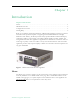
Note This release is "HD-Ready." This means it accepts HD video inputs but scales the output to standard definition resolutions (720x480 or 720x576) or less. How is Video connected? Figure 5 shows the video input connectors on the rear panel. Select the option that matches your video input. If you have a Standard Definition input connector, use S-Video if possible. S-Video generally produces higher-quality input and correspondingly better compressed output than Composite.
Video/Audio Configuration Contrast Boost Enhancer Default = Disabled. Supplements existing Contrast setting. Check to enable. Edge Enhancer Default = Disabled. Sharpens edges in active video region for both Luma and Chroma. Set to Low, Med, or High. Horizontal Frequency Boost Default = Disabled. Amplifies the appropriate video frequency band. • Med – amplifies the middle frequency band of the displayed video. • High – amplifies the highest frequencies of the displayed video.
Frame Rate Frame Rate NTSC inputs (30 or 60fps) 30 30 30 30 15 15 10 1 PAL inputs (25 or 50fps) 25 25 25 25 10 10 5 1 IDR 4 4 4 4 4 4 4 0 Profile Baseline Baseline Main Main Main Main Main Main De-blocking y y y y y y y y Rate Control 60 60 60 60 60 60 60 15 † In general, start in left column and read from left to right. †† Default template.
Video/Audio Configuration Target Frame Rate (frames/sec) • NTSC: 30, 15, 10, 7.5, 6, 5, 3, 2, 1, 0.5. Default = 30. • PAL: 25, 12.5, 5, 2.5, 1, 0.5. Default = 25. This number represents how many frames the VBrick will send out each second to carry the video to an H.264 player. The word target is used because the VBrick can vary its frame rate slightly in response to the amount of motion in the movie or camera output. See the Rate Control Setting parameter below for more details.
176x128 192x144 128x96 176x144 128x96 256x144 128x96 Audio The audio circuit on the H.264 encoder uses mixed signal technology (a combination of analog and digital signals). The encoder has two audio input connectors labeled Main and Aux . The input signals can be either balanced or unbalanced and each has a usable voltage range up to 10 dbU. Various channel configurations and bit rates can be set on the Audio/ Video Configuration > Audio page. The encoder provides controls for mic level vs.
Video/Audio Configuration Note In this release of the H.264 appliance there is one video source and one audio source. The audio source can be one of the audio jacks or both jacks. Also note that there is one program consisting of the audio source and/or the video source. How is Audio Connected? The audio is connected using the input jacks (Main , Aux , SDI , HDMI ) on the rear of the unit. Select one of the following depending on the electrical cable configuration of the input.
What is the Audio Source The audio output mode can be configured to 1 of 3 possible settings: • Stereo – Stereo directs the input left channel to the left channel in the audio stream and the input right channel to the right channel in the audio stream. In this mode, the encoder expects that the two channels are not totally discrete and have audio components that are common to both the left and right channels.
Video/Audio Configuration Automatic Volume The volume is continually monitored and automatically adjusted to Control normalize audio levels as follows. Default = Standard. • Standard – Default. Use for general content which may already be companded (compressed and expanded). • Light – Peak limiting. Best dynamic range. • Moderate – Peak limiting with expansion. Reduced dynamic range. • Aggressive – strong normalization, low dynamic range, most noticeable. • User-Defined – Advanced users only.
Name Stereo as Mono? AAC-HE Sample Freq Bit Rate † High Quality Voice Off 24k 56k 28k Standard Voice Off 16k 32k 18k † Based on Audio Source. †† Default template. Template This read-only field shows the template (if any) that is currently applied. If a template is applied, it will display Parameters Match or Parameters Do Not Match (depending on whether or not changes have been applied).
Chapter 4 Program Configuration A program is a way to group a video and/or audio source that is encoded and streamed over the network. A program represents a video and/or associated audio source. This software release supports one program. As explained on the following pages, the appliance supports two types of program transmission: transmitter mode and server mode. Transmitter Mode In this mode a transmitter pushes the stream to multiple destinations.
Number of Programs Available Read-only. This release supports one program. Maximum RTSP Clients 0–202. Default = 200. Maximum RTSP Bandwidth 0–1000000000. Default = 20000000. Announce IP Address for Transmitters Default IP address to which transmitter announcements are sent. This global announcement IP address is inherited by all other transmitters. Default = 224.2.127.254. Announce IP Address for Servers Default IP address to which server announcements are sent.
Program Configuration Bits 6–7 Reserved for future use. Example To set the Type of Service to all 0s enter 0. To set the Type of Service to all 1's, enter 255. IP Differentiated Services redefine how the historical TOS field is used. Diffserv allows IP networks to provide certain Quality of Service features. Note: If uncertain as to whether the network supports TOS or Diffserv, VBrick recommends setting the TOS to the default value of 0. Programs As noted, this initial release supports one program.
Program Name Lets you define a descriptive name for the program which is added to the announcement. This announcement text is displayed in the Program Guide for other VBrick products. Default = \H Program x . Both Program Name and Session Information allow special character strings to be inserted automatically into these fields. \H or \h – Host Name of VBrick appliance. When the default entry is used, the program is identified by the default VBrick Host Name. Number of Transmitters 0 – 25. Default = 1.
Program Configuration Author A string in the announcement that can be used to identify the author. This string is shown in StreamPlayer. Default = "My Author." Copyright A string in the announcement that can be used to identify the copyright information. This string is shown in StreamPlayer. Default = "My Copyright." Category An encoder can have an announce Category string. This string consists of one or more keywords separated by spaces.
Unicast Time to Live (TTL) The number of hops (between routers) for which an announcement is valid on the network. Multicast Type of Service (TOS) The TOS (Type of Service) can be configured in the IP header to establish packet priority in the network. Unicast Type of Service (TOS) The TOS (Type of Service) can be configured in the IP header to establish packet priority in the network.
Program Configuration transmitting (in the case of multicast) and transmits if the client is reachable and listening (in the case of unicast). The streams are transmitted across the network via the RTP protocol encapsulated in UDP. You can configure up to 25 transmitters per program. Each transmitter can be configured for video and/or audio and the video and audio have separately-configurable destination ports. An "announce" can also be enabled for each transmitter.
Figure 8. Transmitters: Part 1 – Standard Settings SDP File URL Click to play (open) or save the .sdp file. The .sdp file is retrieved via the HTTP server on the appliance. Paste this URL into a browser to launch the stream "out-ofband" using the .sdp file. The URL address for the .sdp file is based on the program and transmitter number, for example: http:// AAA.BBB.CCC.DDD/vbStreamXdY.sdp where: X is the program number, Y is the transmitter number and AAA.BBB.CCC.DDD is appliance IP address.
Program Configuration Destination Select IP Address or Host Name from the dropdown. The actual IP address determines whether the stream will be multicast (e.g. 239.22.118.72) or unicast (e.g. 127.22.118.72). Default = 127.0.0.1 (loopback). If using a Host Name, you must configure a Domain Name Server on the System Configuration > Network page. Transport Type • RTP – Default. Realtime transport protocol provides end-to-end network transport functions suitable for video.
Figure 9. Transmitters: Part 2 – Advanced Settings Announce This section is used to announce the RTSP streams to the local network allowing viewable RTSP announcements in programs like StreamPlayer. The unit must be on the same segment of the network or the router must be configured to retransmit broadcast packets for the announcements to be accessible using the IP address 255.255.255.255.
Program Configuration External Announce This section is used to announce RTSP streams to a network device outside of the broadcast domain. Use Global Announce IP and Port Use Announce IP Address for Transmitters and Announce Port defined on Program Configuration > Global page. If checked, the Destination and Port fields are greyed out. Destination IP Address The destination IP Address or Host Name the announcement is sent to. If using an EtherneTV Portal Server, enter the Portal Server IP address.
Click Here to Play Stream Edit Mode/Read-only. Shown in Edit mode only if the server is enabled. Click once to launch the stream in the QuickTime plugin (using the SDP file). This link will work only with QuickTime 7.0 or higher. If QuickTime is not installed, you will be prompted to download the application from Apple. Choose Server to Configure Select from dropdown list. The number of servers is configured on the Program Configuration > Programs page. 54 Enable Server Check to enable the server.
Program Configuration RTCP Transmit Interval If RTCP Transmit is enabled, this setting tells the appliance how often (in seconds) to send the reports. Default = 10 seconds. Announce Settings This section contains parameters that are used to modify announcements from the appliance. Announcements are advertisement packets that are transmitted by VBrick appliances to other VBrick appliances and VBrick applications such as the EtherneTV Portal Server and StreamPlayer.
56 © 2009 VBrick Systems, Inc.
Chapter 5 Monitor These pages let you monitor the status of various system, network, and appliance components. They also provide access to the system logs and program status. All Monitor pages are read-only and cannot be edited. Note Many of the parameters on the Monitor pages have counters that track dynamic system events (for example Frames Processed on the Monitor > Video/Audio page).
System Information System Model Displays the hardware model number of the appliance. Hardware Revision XX-YY. XX Boot Revision Displays current boot revision. OS Code Revision Displays current OS code revision. = Hardware Revision. YY = CPU Revision. Application Code Revision Displays the revision number of the application code running on the appliance. Current Operational Mode Indicates the current operational mode of the VBrick. The following modes are supported: • Run Mode – Normal operation.
Monitor System Date & Time Read-only. Set date and time on System Configuration > General page. Manufacturing Information Figure 11. Monitor: System – Part 2 User Information Version As displayed. Part Number VBrick part number of appliance. Box Serial Number As displayed. Customer Class As displayed. Manufacturing Date As displayed. Board Assembly Number As displayed. Power Assembly Number As displayed. Lot Number As displayed. Board Serial Number As displayed.
System Restart This table (see Figure 11) tracks the date, time, and restart type (power or reset) of all system restarts. Network DHCP Status Shows DHCP status from System Configuration > Network page. COM Passthrough Operational State The current operational state of COM serial Passthrough port. The possible values are: • Disabled • Enabled Active • Enabled Internal Error • Enabled Rejected • No Dedicated IP Addr MAC Address Displays the appliance's Media Access Control address.
Monitor Primary Network Time Server Successful Update Counter The number of times the time was reset from the primary server. Failed Update Counter The number of times the appliance failed to read the time from the primary server. Current Server Status Status of primary server. Secondary Network Time Server Successful Update Counter The number of times the time was reset from the secondary server.
Detected Video Format SDI or HDMI only. Indicates what is actually connected. This is useful for determining configuration mismatches. Video Rate1 Actual Bit Rate Measured rate in bits per second of the encoded video stream being created by the appliance. Actual Frames per Second Measured rate in frames per second of the encoded video stream being created by the appliance. This rate is rounded down and may indicate 0 for frame rates less than 1 per second.
Monitor Configuration Log This log contains a list of the latest VBrick configuration changes. SNMP Traps This log contains all of the SNMP traps generated by the box whether or not the traps have been emitted. System Events This log contains reports of system events within the VBrick. These events may occur during normal operation and include some details of successful and unsuccessful attempts to access the HTTP and RTSP server as well as a some details concerning server push retries.
Program Status Programs Current Number of Served Current number of HTTP and/or RTSP clients connected to Clients the server. Use Refresh to update page; use Reset Counters to reset to zero. Maximum Number of Served Clients Highest number of HTTP and/or RTSP clients that were concurrently connected since the last time these parameters were Reset. Current Served Bandwidth The approximate calculated bandwidth being used by all Used currently connected clients.
Monitor Transmitter Name Transmitter name from Program Configuration > Transmitter page. Destination IP Destination IP Address or Host Name from Program Configuration > Transmitter page. State • • • • • Bytes Transferred Use Reset Counters to reset to zero. IP Packets Sent Use Reset Counters to reset to zero. Transmitting – no transmitter problems detected. Disabled – transmitter has not been enabled. Ping Failed – ping to unicast destination failed. Ports Not Open – IP port failure.
Current Number of Clients Current number of HTTP and/or RTSP clients connected to the server. Maximum Number of Clients Highest number of HTTP and/or RTSP clients that were concurrently connected since the last time these parameters were Reset. Current Bandwidth Used The approximate calculated bandwidth being used by all currently connected clients. Maximum Bandwidth Used The highest approximate calculated bandwidth used by all connected clients since the last time these parameters were Reset.
Monitor Video Packets Dropped Video packets dropped since session start. Audio Packets Dropped Audio packets dropped since session start. VBrick H.
68 © 2009 VBrick Systems, Inc.
Chapter 6 Troubleshoot Topics in this section Ping Test . . . . . . . . . . . . . . . . . . . . . . . . . . . . . . . . . . . . . . . . . . . . . . . . . . . . . . . . . . . . . . . . 69 TraceRoute Test . . . . . . . . . . . . . . . . . . . . . . . . . . . . . . . . . . . . . . . . . . . . . . . . . . . . . . . . . . . 70 Device Tests . . . . . . . . . . . . . . . . . . . . . . . . . . . . . . . . . . . . . . . . . . . . . . . . . . . . . . . . . . . . . . 71 Maintenance Mode. . . . . . . . . . . . . . . .
Resolved IP Address IP Address of destination. Ping Result Host is alive/not alive. Ping Test Setting Destination IP Address or Host name. Cannot be blank. Number of Packets Number of packets to send for the test (default is 4). PDU Size Protocol Description Unit size of packets, in bytes (default = 64). Transmit Interval (sec.) In seconds (default is sending the packets in 1 second intervals). Transmit Timeout (sec.
Troubleshoot Trace Route Test Result The results of the test appear at the top of the screen. The results include the Resolved IP Address of the Destination Host Name. When the test is finished or stopped, the Overall Result will display the result of the test, such as "Test Done," or "Max hops (=30) Finished," or "Test Stopped," etc. An entry shows the hop number, which is equal to the TTL, IP address (and Host Name if available) of the gateway, and round trip time of each probe.
Number of Loops to Run Number of times to run the test. Intensity Low intensity is faster but runs fewer tests. High intensity runs all tests but may take up to 10 minutes. Maintenance Mode Maintenance mode is automatically launched when the software on the VBrick appliance does not load. A message on the front panel will indicate the appliance is in Maintenance mode. Maintenance mode runs from a reduced functioning kernel that provides limited access to the appliance via the Command Line Interface only.
Troubleshoot Figure 12. Maintenance Mode CLI Limited Run Mode When some error conditions occur, for example when there is a high temperature alarm, the appliance will automatically go into Limited Run Mode and a message will display on the front panel. In Limited Run Mode, you can make configuration changes with VBAdmin, reboot the appliance, or perform other admin tasks to resolve the problem. The only thing you cannot do in Limited Run Mode is stream video.
74 © 2009 VBrick Systems, Inc.
VBrick Systems, Inc.