
Specifications

C2-6104A OPERATION MANUAL
22
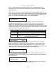
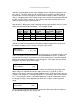
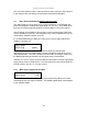
placed in the output video signal – in other words the ‘In’ and ‘Out’ positions and
sizes.
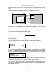
The diagram below should help to clarify the function of these values:
In the example above, ‘In’ has been set to 300,150 as its top-left source co-
ordinate, with a size of 750,400. ‘Out’ has been set to 50,50 (i.e. close to the top
left) with a size of 250,300.
The scaler will then ensure that the whole of the source (of size 750 by 400) is
scaled to the required output (of size 250 x 300).
8.4 Items Associated with the Adjust keyers group
Please note that not all units have this sub-menu – it is only present on units with
overlaying abilities.
Towards the end of this manual you will find a section titled ‘COMMON
OPERATIONS’ – this gives a step-by-step guide to keying out a particular color.
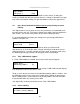
This menu item turns keying On or Off for the current foreground. A keyed image is
in essence one image superimposed over another – such that portions of the top
image are made transparent (keyed out), so that the background image can show
through. The following settings allow you to vary the colour(s) that are keyed out.
This menu item is only present on single-channel scalers – dual and quad-channel
scalers have the layer priority set within the ‘Adjust Windows’ menu.
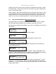
This menu item allows you to swap the foreground and background images when
Lock mode is set to Lock & Mix. It will have no effect in any other mode (since no
background is present).
Adjust keyers
Swap fore/backgrnd [Off]
Adjust keyers
Keyer enable [Off]
IN
OUT
0 1024 0 1024
0 768
0 768