
User's Manual
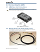

6 AMG1000BHx HD Truck Kit Installation Guide
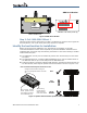
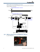
Wiring Harness Installation Overview
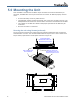
Figure 7 shows the wiring harness installation overview. The following section provides the
detailed installation instructions.
Figure 7: Wiring Harness Installation Overview
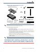
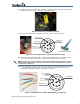
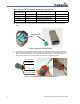
4.3 Wiring Harness Installation Steps
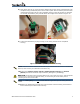
1) Remove dashboard
Figure 8: Remove Dashboard
4
3
1
2
Deutsche 4-Pin
Receptacle
Deutsche 9-Pin
Connector
J1939 Bus
from Engine
Deutsche 9-Pin
Connector
J1939 Bus
from Engine
Pinout:
1 = VBATT
2 = CAN_H
3 = CAN_L
4 = GND
Deutsche 4-Pin
In-Line Connector
Remove pins from Deutsche
9-Pin Connector in vehicle
dashboard and attach to
Deutsche 4-Pin Receptacle
1
2
4
3
VBATT (Red)
GND (Black)
CAN_H (Yellow)
CAN_L (Green)
Vehicle Dashboard
Parking Brake (Orange)
Ignition Sensor (Brown)
1-Wire (Blue) [NOT USED]
Ground (Black)
Molex MiniFit Connector
Plugs into AMG base unit
12 43
56 87
5 = 1-Wire
6 = CAN_L
7 = CAN_H
8 = VBATT
Pinout:
1 = GND
2 = Ignition Sensor
3 = Parking Brake
4 = GND (Battery -)
WIRING HARNESS
Vehicle Dashboard
Attach pins from
wiring harness to
Deutsche 9-Pin
Connector
AMG base unit (Connector Side)
BEFORE AMG WIRING HARNESS IS INSTALLED
AFTER AMG WIRING HARNESS IS INSTALLED