
User's Manual Part 1


6: Installation & Diagnostic Tools
APCD-LM043-8.0 (DRAFT C) 91
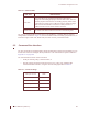
Table 12 Ethernet LEDs
The CCU is equipped with the same LEDs as the EUM but in a slightly different physical
configuration. As shown in Figure 42, the CCU indicator LEDs are closely grouped and are, in
order left to right: Power LED, Radio LED (not used on CCU), and Network LED.
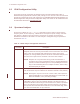
6.2 Command-line Interface
The CCU and EUM are equipped with a simple command line interface through which you can
monitor unit status and configure all unit parameters. The command-line syntax is defined in
Appendix C on page 189.
The command-line interface can be accessed
• locally or remotely, using a Telnet session, or
• directly, through the DB-9 console port on the CCU, using a PC equipped with
terminal emulation software, using the console settings specified in Table 13.
Table 13 Console Settings
LED State Ethernet Status
Link LED
If the Link LED is ON, the Ethernet physical connection is
configured and working properly. If the Link LED is OFF, then the
Ethernet physical connection is not working properly, which could
be because the wrong type of cable was used (a straight-through
cable at the EUM instead of a crossover cable) or there is a
problem with the host or device Ethernet interface.
Traffic LED The Traffic LED flashes whenever the link is transferring data.
Bits per second 9600
Data bits 8
Parity None
Stop bits 1
Flow Control None