
User's Manual Part 1


9: Installing the EUM
APCD-LM043-8.0 (DRAFT C) 155
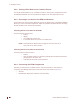
1. Connect the end-user’s PC, shown in Figure 59, by attaching the crossover Ethernet
cable with ferrite bead that is included with the kit between the Ethernet port on the
end-user’s computer and the Ethernet port on the EUM.
Figure 59 Connecting the End-user’s PC
2. Check the Ethernet LEDs on the back panel of the EUM to ensure the Ethernet
connection between the EUM and the end-user’s PC is active. Refer to Table 26 for
an explanation of the Ethernet LED status displays.
Table 26 Ethernet LED Status Displays
3. When attempting to send data to, or receive data from, the Internet, check the
Ethernet Traffic LED to ensure data transmission is taking place. This LED flashes as
data traffic passes between the end-user’s PC and the EUM. The network LED on the
front of the EUM also flashes and is more accessible than the Traffic LED on the rear
of the EUM.
Ethernet LED Status
Ethernet Link LED This LED is lit when there is a correct connection to
the computer, and both ends are powered ON.
Ethernet Traffic LED Flashes when data passes through the Ethernet
connection in either direction.
Denotes reserved ports. Do NOT
Connect.
Computer
2
AC/DC Adapter
Power Bar
EUM
Step 1
Antenna Cable
Step 4
Ethernet Cable
Step 3
AC Cable
Step 2
DC Cable
Antenna
Bracket
Antenna
Connector
DC P
ower
Connector
Ethernet
Connector
4
4
1