
User's Manual Part 1


22 APCD-LM043-8.0 (DRAFT C)
3: Detailed Description
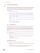
3.2.2 Switched Ethernet Mode
Figure 13 shows the LMS4000 900 MHz Radio Network transmission concept for Switched
Ethernet mode.
Figure 13 LMS4000 Transmission Concept - Switched Ethernet Mode
In Switched Ethernet mode, the Ethernet and radio interfaces of the CCU belong to the same
Ethernet domain, with a switch between, enabling any number of IP subnets to be supported
on either or both sides of the CCU. This flexibility allows placing all subscribers on public IP
addresses and “hiding” the radio network from the subscribers, without using public IP
addresses for the EUMs and CCUs. A different subnet may be set up on the Ethernet side of
the CCU to enable ISPs to manage and monitor all devices (CCU and EUMs) on the radio
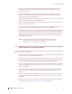
network. Figure 14 illustrates the above configuration.
Figure 14 Switched Ethernet Mode with Multiple Subnets
EUM Host
PC
EUM Host
End-user
LAN
PC
EUM Host
"Switch"
CCU
CCU Ethernet port
CCU Application
CCU3000
Antenna
EUM
Switch
Internet
subscriber
DHCP, RADIUS Server
Router
Interface 0/1
192.0.2.1/24
172.16.6.10/22
Interface 0/0
10.2.23.1/24
172.16.6.1/22
GW 172.16.6.10
192.0.2.7/24
192.0.2.5/24
172.16.6.101/22
GW 172.16.6.10
192.0.2.101/24
GW 192.0.2.1
EUM
subscriber
172.16.6.102/22
GW 172.16.6.10
192.0.2.102/24
GW 192.0.2.1
Gateway for EUMs & Suscribers
192.0.2.1