
User's Manual Part 1


4: IP Network Planning
APCD-LM043-8.0 (DRAFT C) 63
The radio networks for every CCU and the CCU Ethernet network, up to the router port, are
part of a single Ethernet broadcast domain. All Ethernet devices connected to the same router
port through Ethernet switches and radio networks contribute to broadcast traffic on this
network, as shown in Figure 33 and Figure 34.
Different IP subnets can be assigned to different devices in the radio network, if required. For
example, EUMs may be assigned to one IP subnet for management and subscribers to
another, or even to multiple IP subnets. This requires configuring the gateway router with
multiple IP addresses and subnets, and routing between the subnets. Note that all traffic
between the subnets (from a subscriber to the attached EUM for example) must travel to the
router and back, which—especially if this involves backhaul equipment—may introduce
unexpected latencies in communication, noticeable in throughput tests.
DHCP can be used to assign IP addresses to all subscribers. A CCU or router can relay
DHCP, or the DHCP server can be placed in the broadcast domain. If all subscribers’ IP
addresses are to be assigned from the same pool, then a simple implementation of DHCP can
be used. If separate IP address pools are to be used for each radio network, then alternative
approaches to DHCP need to be considered. This is beyond the scope of this document.
Please contact WaveRider for further information.
If subscribers’ IP addresses and subnets are obtained through DHCP and are on a separate
IP subnet from the EUMs, the subscriber IP network can be reconfigured by revoking the
DHCP leases and reconfiguring the DHCP pools, the gateway router, and any other
equipment on that IP subnet. This makes the network more scalable within limits.
In large networks, Ethernet broadcast traffic could become a major issue. Therefore, it is very
important to plan for the expected size of the network when selecting Switched Ethernet
mode. Some guidelines on network size are given below.
In summary, while Switched Ethernet mode offers easy integration to smaller networks with
network size limited, implementing this mode in medium to large networks requires a higher
level of planning and implementation skills.
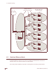
Figure 33 Switched Ethernet Mode – Ethernet Broadcast Domain for a single CCU
CCU3000
Antenna
EUM
Switch
Internet
subscriber
Serv ers (e.g DHCP, RADIUS) and/or
other devices connected to
switch(es)
Gateway Router
Interface 1
Interface 0
EUM
subscriber
Ethernet Broadcast Domain,
1 or more IP subnets