UHF Transceiver TR700B INSTALLATION AND OPERATION GUIDE FOR SYSTEM OPERATORS
Proprietary to VCom Inc. All rights reserved. No part of this publication may by reproduced in any form or by any means or used to make any derivative work (such as translation, transformation or adaptation) without written permission from VCom Inc. VCom Inc. reserves the right to revise this publication and to make changes in content from time to time without obligation on the part of VCom Inc. to provide notification of such revision or change. VCom Inc.
Thank-you for purchasing this product and welcome to VCom! You have chosen an innovative solution from a leading technology design center in the ongoing TV & data delivery revolution. No doubt you’ve been thinking that the future of your television delivery system includes new technologies such as Digital TV, Internet Over Cable, Wireless Cable.
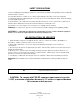
SAFETY PRECAUTIONS 1. Before installing and operating this equipment, read all Safety, Installation and Operating sections. Retain this manual for future reference. 2. Follow all instructions — Failure to do so may result in damage to the unit or severe personal injury. 3. Servicing should not be attempted by the user. There are no user serviceable parts inside. Refer all servicing to factory qualified personnel. 4.
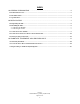
INDEX 1.0 GENERAL INFORMATION .....................................................................................................6 1.1 Functional Overview ......................................................................................................................................6 1.2 Module Features .............................................................................................................................................6 1.3 Specifications......................................
The VCom TR700B is an UHF Transceiver for use in wireless systems. The TR700B integrates an LNA, upconverter, power amplifier, RF and IF diplexers to provide a one-box solution for two-way wireless RF communications. The TR700B and antenna are situated outdoors and connected to a cable modem indoors by standard RG-59 cable. A single RF connector on the weatherproofed enclosure provides the interface to the transmit/receive antenna for rapid setup.
! " TRANSMITTER SPECIFICATIONS IF Input Frequency 36-42 MHz (TR700B) 44.375-50.375 MHz (TR700B-IF1) 710-716 MHz RF Output Frequency Linear Output Power +24 dBm at RF port Output P1dB Spectral Mask Gain Gain Flatness (Frequency Response) Gain Stability over Temperature Phase Noise Spectral inversion IF Level for RF Activation RF Activation/Mute Response Time +27 dBm at RF port FCC CFR 47 Part 27.53 20 ± 2 dB at 23°C ± 1.0 dB over 710-716 MHz ± 2.
#! $ %& # Carefully remove the equipment from its packing material and set it on a solid surface, such as a table or desk. If it appears damaged in any way, notify the carrier, and keep all packing materials for inspection by the carrier’s agent.
% & Mount the antenna according to the manufacturer’s instructions. The TR700B is intended for use with planar arrays and Yagi antennas. Please consult table 2.2B for further information. Table 2.2B: Antenna List Transceiver Power [Watts] 0.25 0.25 0.25 [dBm] +24 +24 +24 Antenna Type Antenna Gain Yagi Flat planar array Window mount planar array [dBi] 10 dBi 9 dBi 7 dBi Included with the TR700B unit is a self-adhesive label for application to the antenna.
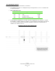
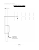
) & Connect the TR700B to the Antenna via the N-Connector DIAGRAM 2.3A: CONNECTION TO THE ANTENNA VCom Inc. TR700B Manual; ml_tr700B_02 (March 2004) Approved: C.H.
*) & + ), - Connect the TR700B F-Connector to the power inserter, located indoors with the cable modem. Connect the power inserter to the Cable Modem. If the TR700B is equipped with the optional self install feature, insure that the power inserter is connected to the Cable Modem, only after the antenna is aligned.
./ ! "%) Many transceiver problems can be attributed to environmental conditions (including vibration), which can loosen cables and permit moisture to penetrate the connectors. It is highly recommended to seal the connectors using a technique similar to the one described below. This will provide moisture protection and keep the connections tight. For your convenience, VCom has provided two 6 inch lengths of rubber self-amalgamating sealing tape to use on the two connections of the TR700B.
STEP 3 When done, the connection should be tightly wrapped with tape, with a good seal to the cable. DIAGRAM 2.5C: WATERPROOFING CONNECTION – STEP 3 VCom Inc. TR700B Manual; ml_tr700B_02 (March 2004) Approved: C.H.
/ / 0 3 1 2) + )0 - VCom warrants its products to be free from defects in workmanship or materials for a period of two years. The warranty begins on the date of the original shipment from VCom to its customer. No claim may be allowed for expenses incurred in installation or use. No other expressed or implied warranties shall apply to the goods sold.
! )& % / 3 6 -! Items returned beyond the warranty period or items that do not qualify for warranty service are subject to additional out-of-warranty repair charges. Descriptions of these charges and warranty exemptions are below: 1) Repair turnaround time is typically 5-14 business days after receipt of the item at VCom. A Flat Rate Repair Charge will apply to all out-of-warranty items. Flat Rate Repair Charges are subject to change without notice.
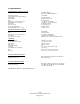
150 Cardinal Place Saskatoon, Saskatchewan S7L 6H7 Canada Tel: (306) 955-7075 Fax: (306) 955-9919 www.vcom.com sales@vcom.