
User's Manual


VCom Inc.
TR850 Manual; ml_tr850_01 (January 2005)
Approved: C.H.
11
*)&+),-
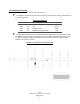
Connections to the TR850 are made as shown in Diagrams 2.3A and either 2.4B or 2.4C depending on which
power supply and inserter came with the TR850.
The power inserter has three connections:
DC POWER Connect to wall adapter with RG-59 cable with F connectors
TO MODEM Connect to cable modem
TO TRANSCEIVER Connect to TR850
WARNING!
If the power inserter is not connected correctly, the TR850 will not operate,
and there is the potential to damage the cable modem.
Ensure that all wires and cables are hooked up before plugging into the
AC adapter/power supply (i.e. hook up to the power supply last).
After connection, both connectors MUST be waterproofed with the supplied rubber sealing tape. See Section 2.5
for details.
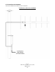
DIAGRAM 2.4A: CONNECTION TO CABLE MODEM VIA POWER INSERTER USING PS24V750MA-01