
Installation Manual


HW Installation manual Rev 3.10
VECOS Europe BV, Esp 237, 5633 AD EINDHOVEN, The Netherlands Page 10 of 19
4. Terminal cabling
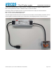
4.1. LBC 3.0 Terminal
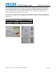
The LBC 3.0 terminal can be connected with the same cables as used for connecting HUBs, except for the TCP-IP
Network cable, that needs to be a CAT5E or higher network cable and NOT the flat cable used between the HUBs.
Between the 2 RJ45 ports, A switch and jumper is placed between the 2 RJ45 ports,.
The Jumper is to activate the RS485 termination (default placed), remove the jumper if the LBC 3.0 is not connected
to the end of the RS485 cable, in that case terminate the 2 HUBs at the end of the RS485 communication bus.
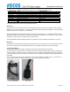
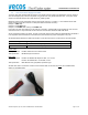
4.2. LBC 3.0 Key switch
The LBC 3.0 contains the emergency open switch:
Middle position is off.
To front: Block 1 active.
To back: Block 2 active.
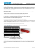
To indicate the status active state, a lock symbol is placed in the top line of the display
with a 1 or 2 next to it:
If one of them is active, the HUBs that are configured with the dipswitches to check the Block 1 or 2 signal will activate
all locks attached to that HUB accordingly.
There is no need to connect the external key switches anymore
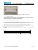
If more than 2 emergency switches are needed, also extra power supplies can be added, so the maximum number of
locks on 1 key signal are not exceeded.
When the Key switch is active, the locks will be activated and will get hotter. The locks have 2 protections:
1. The software makes sure the lock isn’t activated more than 15 minutes. The software makes sure the lock
isn’t activated more than 15 minutes.
2. In case a lock gets too hot, a hardware protection will disable the coil of the lock until it’s cooled down again.