
Installation Manual

HW Installation manual Rev 3.10
VECOS Europe BV, Esp 237, 5633 AD EINDHOVEN, The Netherlands Page 7 of 19
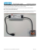
2.2. Connect the Power Supply to the HUB
To be sure everything operates well also when a lot of people scan their cards (only applicable for the V3+ series) or
when the emergency key is used, it’s important not to connect too many HUBs after each other,. If the power cable
needs to be extended, always use at least 2x2.5mm
2
[AWG13] cable.
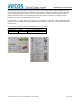
Maximum number of fully used HUB’s from the power supply output is 1, or better 1+1. This makes sure the white
power connector never gets more than 7A load (max load for the white connector).
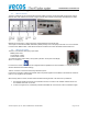
Example 1: PWR-HUB
Example 2: HUB- PWR-HUB
Example 3: HUB-PWR-HUB <nothing> HUB-PWR-HUB
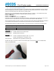
If the HUB is not fully used (meaning no 24 locks are connected), multiple HUBs can be applied, but never connect
more than 6 locks in 1 loop and never connect more than 24 locks from where the PWR cable starts.
As last, the terminal needs to get power, the LBC 3.0 terminal uses the same cabling as applied between the HUBs. It
is not important where the terminal is connected to the power because its power consumption is very low.
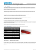
All standard cables between the HUB’s and the LBC 3.0 are the same, the CUL versions are for the USA & CAN:
VECOS Ordering code Description
CL16061/1 or CUL16061/1 HUB Data Cable 3.0m [9.8 ft]
CL16062/1 or CUL16062/1 HUB Power Cable 3.0m [9.8 ft]
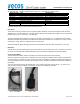
Power Cable:
Cable specification : UL2648 16AWG 2C Colour: black & Red
Jack specification : WR MPC4 Nylon 66 UL94V-2
Data Cable:
Cable specification : UL20251 8C 26AWG flat telephone cable, 2,5 * 9,0 mm.
: UL2725 8C 26AWG VW-1 round cable, 5.0 mm.
Jack specification : 8P8C Modular Jack gold plated, squareness type.
As Data cable, also a normal UTP CAT5E or CAT6 network cable can be used, but never use a shielded cable,
always an unshielded cable.