
Installation Manual

HW Installation manual Rev 3.10
VECOS Europe BV, Esp 237, 5633 AD EINDHOVEN, The Netherlands Page 9 of 19
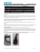
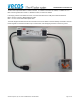
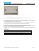
3.3. V3 Controller connections
Both power connections and both communication ports are the same (internally connected parallel),
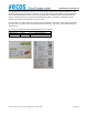
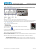
3.4. V3 Controller settings
There are multiple ways to control the block open signal (also called the Emergency Open signal) of the V3 locks
connected to the HUB V3, see the table below for the possible settings.
Every HUB that has an Block signal setting selected, will pass on the selected Block signal to the Locks. If the signal
becomes active, all locks connected to this HUB will be activated.
For V3 locks, this needs to be active, because if the terminal is broken, the lockers can’t be opened in another way.
For V3+ series this optional, because with a Master badge on the lock itself it still can be opened .
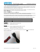
The communication lines of the HUB V3 and V3 Locks need to be terminated at both ends of the entire
communication bus. This means max. TWO no 4 switches are ON in the entire bus, most of the time just 1 because
the terminal is connected to the other end and has default termination active.
A simple rule: if there is only 1 RJ45 (data cable) connected, then this is the end of the bus and termination needs to
be activated.
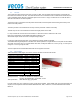
Dip switch settings:
No
Function
Default
1 Key switch input connected to Block open OFF
2 Bus Block 1 signal connect to Block open OFF
3 Bus Block 2 signal connect to Block open OFF
4 Line termination OFF