., {Z~m ~~~ffiJ~~ m(IDilloo[ID ~(ID~~~TIT 00
ZCB SINGLE OOARD
COpyright 1980 by Vector Graphic Inc. All rights resetved. Disclaimer Vector Graphic makes no representations or warranties with respect to the contents of this manual itself, whether or not the product it describes is covered by a warranty or repair agreeJIW::!nt.
Vector ZCB Single Board Computer REPAIR AGREEMENl' The ZCB Single Board Computer sold hereunder is sold lias is", with all faults an:] without any warranty, either expressed or implied, including any implied warranty of fitness for intended use or rerchantability. However, the above notwithstanding, VECTOR GRAPHIC, INC.
vector ZCB Single Board COmputer FORlKJRD Audience This manual is intended for canputer distributors, or others with at least a moderate technical knowledge of small I <:XIlplters. It will describe what the Vector Graphic ZCB Single. Board Computer does in the context of a canputer system, how to use the board both in Vector Graphic and in other 8-100 systems, arrl how the board circuitry works. Organization Rev. 1-8 6/11/80 Each section is written at a uniform level of technical depth.
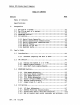
Vector ZCB Single Board canputer TABLE OF CCNr:mrS Section Table of COntents Specifications I. Perspective 1.1 1.2 1.3 1.4 1.5 The ZCB as a system •••••••••••••••••••••••••••••••••••••••• l-l The ZCB as part of a system•••••••••••••••••••••••••••••••• l-l CPU section •••••••••••••••••••••••••••••••••••••••••••••••• 1-1 EPROM/RAM section •••••••••••••••••••••••••••••••••••••••••• 1-2 I/O section •••••••••••••••••••••••••••••••••••••••••••••••• l-2 1.5.• 1 1.5.2 1.5.3 1.5.4 1.5.5 1.5.6 II.
Vector ZCB Single Board canputer ~ Section 2.4.5 2.4.6 2.4.7 2.4.S 2.4.9 2.9 How to connect most low speed acoustic couplers ••••• 2-15 Connecting additional RS-232C handshaking lines ••••• 2-15 USing the Parallel Ports •••••••••••••••••••••••••••• 2-1S Connecting Sprint 3 to ZCB •••••••••••••••••••••••••• 2-19 Connecting vector MP to ZCB ••••••••••••••••••••••••• 2-19 Spare Chip and Patch areas ••••••••••••••••••••••••••••••••• 2-20 III. Theory of Operation 3.
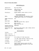
Vector ZCB Single Board COmputer SPECIFICATIONS-System COmpatibility: Most S-100 systans. Power Requirements +8VOC @ 970 rna. (typ.) +16 VDC @ 120 rna. -16 VDC @ 80 mao Availability: Shipped assembled, tested, burned in; no kits. SPECIFICATIONS-EPRCM/RAM Menory 65536 bytes addressable, 1024 bytes RAM on board, 3 EPRCM sockets on board, up to 12K addressable EPRG1s included with none bJard Menory Speed RAM: 300ns. EPRCI'1: User selected (450 ns.
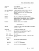
Vector ZCB Single Board Carplter Static RAM Fully compatible MWRlTE Jumper option to generate MWRITE on board StaOOard: option enabled. Wait state generation for memories slower than 300 ns. 3 options: generate one wait state on each bus cycle, generate one wait state after each Ml instruction, generate no wait states. StaOOard: generate one wait state after each Ml instruction. .
Vector ZCB Single Board COmputer Synchronous Rates Synch detect OC-56K. can 8251 be wired for internal or external synch. SYND~ line is not connected. Clock tbt now connected to the external 'WOrld as required for synchronous operation. parity Even, odd, or none, prrts 2-8 bit, 2-4 bit can be prograrrured as 3-8 bit. an 8255 parallel I/O controller dlip. Uses Pc>rt .
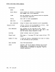
Vector ZCB Single Board COmputer I. PERSP&:TIVE 1.1 '!be ZCB as a system The Vector Graphic ZCB Single Board Computer provides the capability of a canplete canputer systan on a single board. The ZCB contains what you would normally find on a CPU board, a PROM/RAM board and an I/O board, all contained on one S-IOO bus compatible board. The ZCB contains a Z-80A microprocessor, 1024 bytes of static RAM menvry, sockets for up to 12K of PRG1, one serial I/O port aOO three 8-bit parallel ports.
Vector ZCB Single Board canputer dynamic IreIl'Ories, such as Vector Graphic's 64K IreIl'Ot:y board. Simplicity of design has been stressed to enhance reliability of operation by the use of MSI aoo ISI integrated circuits. 1.4 P.RG1,!RAM section The PROM/RAM section features lK of on-board RAM mem::>t:y (using 2114's) aoo up to 12K of PRCM, RCM or EPRCM. Note: For the purposes of discussion in this manual, the terms PROM, EPR.CM and RCM may be used interchangably.
Vector ZCB Single Board Ccmputer It is not within the scope of this manual to detail the functioning of the 8251 USART chip, nor to teach the theory of serial carmunication. In order to write your own camnunications software or to rrodify the ZC8 serial port, you will need to be thoroughly familiar with this
Vector ZCB Single Board canputer 1.5.4 RS-232C theo;y This manual cannot describe the RS-232C protocol in detail. For a full description, obtain a copy of the RS-232C EIA S'I'ANDA.RD document, published by Electonic Industries Association, Engineering Department, 2001 Eye Street, N.W., Washington, D.C. 20006. Alternately, if you have access to Datapro or Auerbach reports on communications, they contain thorough articles describing the protocol and its implications.
Vector ZCB Single Board COmputer from the original purpose for RS-232C - to connect a terminal with a communication device such as a modem. A computer does not have to be involved at all. Since a canputer can either play the part of a terminal, when connected to a modem, or it can play the part of communication equiprent, when connected to a tenninal, accmputer serial tx>rt can be used either as LeE or DI'E. However, a given serial {X>rt can only be wired up as one or the other at anyone time.
Vector ZCB Single Board emrputer handshaking line. 'lbere is one spare RS-232C recelve~r-arid one spare RS=-232C driver available qn the board which can be used to connect one input and one output handshaking line. For the large majority of applications, no additional RS-232C lines will be required other than those already conriected to active canponents on the ZCB board. 'lbus the serial ports can very often be used as DCE RS-232C input/output ports without modification.
Vector ZCB Single Board Computer language instructions within software prepared for specific applications. Output is latched on the board, so that after an OUT instruction is executed, the eight bits of data remain available to the external device until the canputer changes it. Input is N
Vector ZCB Single Board Canputer II. 2.1 USER'S GUIDE Introduction The User's Guide explains how the board functions as manufactured and tells how to change various user selectable q>tions by neans of jumpers and switches to fit other than standard requirements. The User's Guide is divided into 3 sections to cover the three main areas of board operation: CPU section, EPRCM/RAM section and I/O section. 2.1.
Vector ZCB Single Board canputer 2.2.2 MWRITE enable/disable Jumper area: 0 Connections as manufactured: jlll'llf'ler installed Function: when connected, the ZCB board will generate the MWRITE signal (S-IOO line 68). You will want to disconnect this jLnTlper if there is some other source of MWRITE in the system, such as a front panel. Options: if r+1RITE generation is not wanted, cut the jumper in area D. 2.2.
Vector ZCB Single Board Canputer 2.3.1 2708 EPROM Addressing 270S type EPROMs are the easiest type of PRCM to chose ••• they are the factory standard and the roard is prejumpered to use them. The standard jumpering of the ZCB provides for the Vector Graphic 4.0 Monitor addressed at EOOOH.
Vector ZCB Single Board canputer Area F EPRCM/RAM Socket Pad Chart Pad Pad Pad Pad 1 6 2 3 connects connects connects connects EPRCM 0 (U20) to its address. EPRCM 1 (U2l) to its address. EPRCM 2 (U22) to its address. RAM (U24,25) to its address. If you want to use 2708's and change memory locations outside of the standard block (EOOOH-FFFFH) use the following procedure. 1) Determine which 8K memory block you want to use from the 2708 Base Address Chart below.
Vector ZCB Single Board Computer _.3.3 2716 EPROM Addressing To use 2716 1 s in the ZCB, follCM the procedure outlined belcw. 1) Consult the 2716 Base Address Chart (below). addresses allowable with 2716 1 s.
Vector ZCB Single Board canputer 2.3.4 2732 EPROM Addressing To use 2732 1 s in the ZCB, follow the procedure outlined below. 1) Oonsult the 2732 Base Address Chart. ' This shows the base addresses allowable with 2732 1 s. 2732 Base Address Chart Addresses Area H Jumpers OOOOH-7FFFH 8000H-FFFFH 1-2-3,3-9 1-2-3,3-8 Area I Jumpers 8-3,7-2,6-1 8-3,7-2,6-1 Area J JllllJ?E:rs 3-4,1-7 3-4,1-7 2) With the base address chosen, jumper areas r H, I and J as per the 2732 chart and cut away the old jumpers.
vector ZCB Single Board Ccmputer 2.3.6 Phantom enable/disable Jumper area: C Connections as manufactured: jl.lIl'p:red. Function: Allows generation of phantan on 5-100 bus line 67. When enabled, phantom disables other system rrem:>r.y toards. This is useful when you want to jump to a particular EPRCM on system };X)Wer on/reset. Qptions: to disable the generation of the phantan signal cut jumper between both pads of jumper area C. 2.3.
vector ZCB Single Board Computer selecting the £X'rt addresses desired. For standard use in vector Graphic Microcomputer Systems, the default addresses are adequate. For more involved systems, it may be necessary to change port addresses. This is accomplished by merely changing SCIre jumper connections on the ZCB ix>ard. The first thing to do is to decide what port addresses you wish to use.
Vector ZCB Single Board Ca!puter 2.4.2 Address mirroring disable/enable Jumper area: 0 Comections as manufactured: function enabled: pad 3 comected to pad 2 Function: emulates 8080 address mirroring: 8-bit I/O p::>rt address is mirrored on the high a:3dress bus during an I/O instruction. Options: To disable address mirroring, cut the jumper between pads 3 and 2 and jumper 1 and 2 together.
Vector ZCB Single Board carputer Additional RS-232 haroshaking lines available The following RS-232 data and handshaking are available at the serial I/O connector. J-2 Pin NulTber r:&-25 fl:1Uivalent 14 15 7 11 13 12 10 3 2 20 6 4 5 7 Narre BS-232 ~ignation Direction crs out In In OUt In OUt GID NA RxD TxD Dl'R ISR RI'S Transmitted Data Received Data Data Tenninal Ready Data Set Ready Request to Sen::] Clear to Sem Groond Parallel I/O Connector Pincut Chart 1. 2. 3. 4. 5. 6. 7. 8. 9. 10. N.C.
Vector ZCB Single Board Cailputer ~.4.3 Asynchronous serial baud rate selection You select the desired baud rate through a combination of hardware switches and software. If you are using the standard q:>erating systems and Extended Systens Monitors for Vector Graphic Systens, however, you need only be concerned with the hardware switches. The hardware switch is located in the upper left hand corner of the board. It is labeled "Baud Rate Select".
Vector ZCB Single fbard Garputer Always insert the connector so that the ribbon cable anerges toward the of the board. You can double check this by checking that the "1" on the connector corres{X)nds with the "1" printed on the board next to the socket. Then install the OB-25 at the other end of the cable into one of the available sockets at the rear of the camputer, or wherever convenient. .!92. '!he board canes with one serial I/O cable.
vector ZCB Single Board Computer Many peripherals hold either or both lines 4 and 20 at +12 VOC. This allows an alternate method of providing the peripheral with +12 VDC on lines 5, 6, and/or 8. Simply rrake the appropriate connection{s) at the back of the peripheral. This can be done by soldering jumpers within the DB-25 connector or external to it. For example, to provide +12 VDC on lines 5 and 6, you can connect pin 4 to 5, and pin 6 to 20.
Vector ZCB Single Board canputer 1200 baud or less: Use a 25-wire ribbon cable, with male IE-25 connectors at both ends. (TI 810 has a female connector at its rear, as does the ZCB Serial I/O cable.) On both ends of this rnale-to-male cable, pin 1 is the u~r left-harrl pin when looking bDward the connector's pins and holding the connector so that the longer roW' of pins is on top.
Vector ZCB Single Board canputer L..4.5 How to connect many low sp:ed asynchronous acoustic couplers and IOOdems This section is applicable to many acoustic couplers and IOOdems which carry out asynchronous canmunications at rates of 1200 baud or less. It is almost always applicable for asynchronous couplers and modems operating at 300 baud or less.
Vector ZCB Single Board COmputer RS-232C name Source Protective Ground Transmitted Data Rece i ved Data Request to Serrl Clear to Send Data Set Ready Signal Ground Received Line Signal Detector (Reserved for Data Set Testing) (Reserved for Data Set Testing) (unassigned) Secondary Received Line Signal.Det.
Vector ZCB Single Board COmputer It is ~rtant to note here that in the RS-232C protocol, any given line has one name, regardless of your point of view. For example, although a m:rlem, which is a kind of Data Comnunications Equipment (" DCE" ), rece i ves its data on line 2, line 2 is still called Transmitted Data.
vector ZCB Single Board Ccmputer anything. Software can tell that the 8251 is ready to transmit by monitoring the TxRDY bit in the status byte, or by being interrupted by the TxRDY 8251 output (pin 15). For infotmation on the 8251 status byte, refer to one of the 8251 references rrentioned in the Perspective section of this. manual. Remember that if you are connecting a serial port to a rrOOE!m or other Da.
Vector ZCB Single &:lard canputer The Jl 34-pin connector is I1UIl'bered beginning with the front left-hand pin as nuI'li:>er 1. The back: left-hand pin is number 2. 3 and 4 are the next two pins to the right, and so on, with odd pin I1UIl'bers in the front and even pin numbers in the back. The connector cable is set up so that the lines are nurrbered 1 to 34 fran left to right. The functional definition of each line is as follows: Parallel I/O Connector Pinout Olart l. 2. 3. 4. 5. 6. 7. 8. 9. 10. 2.4.
, Vector ZCB Single Board Co11puter 3) Fasten the other end of the cable with the DB-25S connector to the rear panel of the canputer with the hardware provided. 4) 2.9 Label the connector liMP Signal Connector. II Spare chips and patch areas Socket U26 is large enough for a 14-pin DIP. None of the holes are connected to anything on the board wi th the exception of GND and +5V. There are a number of unused gates on the ZCB board which yru may find useful to use.
Vector ZCB Single Board Canputer III. 3.1 THEX)RY OF OPERATlOO system Operation Block Diagram Since the ZCB combines the circuitry normally found on three different 5-100 boards, its operation is somewhat complex. In order to make the theory of operation a bit easier to follow, \E are first including a block diagram of the major circuit areas of the ZCB to get an idea of the overall system operation. This explanation will be follo\Ed by an area by area break.down.
Vector ZCB Single Board canputer reason why there is such a disparity between the signals required vs the signals available are evident when you consider that the S-IOO bus was evolved around a system based on the 8080 microprocessor using static memory. Our system is based upon the faster, more versatile Z-80 using dynamic rrem::>ry. However, the signals required are easily provided for. The I/O CONTROL block (sheet 6) consist of decoders and flip flOj?S which do two separate things.
Vector ZCB Single Board Oomputer except for 110 baud, are obtained by successively dividing this frequency in half using Ul, which is 74LS393 binary counters. The clock frequency for llO baud is generated by dividing the frequency for 1200 baud by 11. The desired frequency is selected by a DIP switch for each serial port, and applied to the TxC am RxC pins of the 8251.
Vector ZCB Single Board Qamputer IV. APPENDIX AND SCHEl1ATICS APPENDIX A change has been made in the ZCB PRCM socket addressiI'B as the boards are currently being shipped. '!he third socket (U22) has been reconfigured to accept an 83l6E302 type 2K ROM chip addressed at EOOOH. Sockets U20 and U2l remain configured for 2708's at E800H and EeOOH respectively. Rev.
• t I l.! rl~ - ( ~~ r----....L-..., I I:P f-~~/_+-+_ ::t Vl t-+ f------.. lIoij I II . I~ r-----.....
I A~ 3° AI '31 MA¢ ..Nf A I Awl 3.l 111 A~ A3 33 '3'1 .,Nt A A~ -r.5 V _-...~/:.,.I RIO IV" i , ~5 ... , 3.s3" MASMA6 ,1.7 3"1 ..11 1<7 A9 13~ I'll A 8 ~13~7__________________________~______ ,~A~ AIO i "10 )g 31o~ A 1'3 i '3 AI"I : 'I .,t1A II{ A /4. , ('5,.J8) ,.4 A~ '--:-'I\l wAIT - - - - - - - - - - 0 "'-JAil AA 10 MArl P1 A Il. /~" I J ,.1111 4~ _ _--::;.1::..L'_. ~!oj Q 1 i.. is ,N1A/5 ! D¢ U23 2:80-A DI Ol. 03 ny 111 ftlp·1'o I,.. #f1J)..
g T.l8 ~ __ ~ ________ 4/1( " ~~~u~ __________________________________ 3T1S II /11 ..... 0 ~-1 "01 (slit) __~__~~~~~~~~L-~-J 8 05 ~(~5~H_/)____________~~ (~"'i') 3 t'\v,,11 fi(5';1T (Sp..,) .5 , RONI ~ (:~s:!!..uq~')~/~-:::~ ~ (S~> 3 a 1:>----' -;;;;;;;- (5,-116;;..;..)___""'1 ~ (s:..,;.fJ6...,:1--,:...j S D-4 1"t4 HeEl ),,/9 a VI t!t. C :) I'-.:. -r ,Q.
(HII) (S iJt) j II ~7 ~ !S' 5 :>'7 i (~ .l. .N/) 9 If ("5#/) (7 37 r BA l A). ,BA Jb 37 AI <::( Il. 37 (::SIN) 3- 7'1 ""1/ :l 1'13 SA "I ¥ 3 13 ,7 7 (::Sill) (. l~ 7 I" - (SI.J~ 1 S/.! 1 iff..fo).J('f e ('!illl) ~q 9 <(Sill) il IS~ 9 I (S~/) '{~ lA1' 11 (:5/./1) ,"1 " ~ , I (~IJI) B ~7 ~ i ~I'f c;.:Q ~~,ti1 IS (~ ;/1) t:A~1 1'1 I 1\ L/2 J2:. r" 7'1 LI +5V '/'17 fl.
+5V 'I,. ,Nl.l 7~Lf7If~ J.. D PA. 1':1 S '$ pa) 1 ;;~ Ii )O-----~.'?'. ---~-- "" ·7'"'! r--"'--"';=-l ,;I ----------~I)Cr: ~,b oJG. ( , ~ 13 Poe I CJ.~ ~...,o ,Y.? KA t - - - - - - R£ SeT t' '1L$I'I i R11..IOO.,j\. ~____~~~~__~93 ~~~~ PRESEt SA 15 T~,'-S V 9 (. (.s~3) 8 H ~--,3 !> 13 " 1". 7'f L 1-)..Q y:J. 7~L~ 7'-; q 13 +6i1 13AI.3 1 (S.;.I!,J " ~--,\ t-sv +S'v -+$ v ......"fV\.r---+---4 ,..----j.!._ +5 v _."" A"'----'- _ l r.s 110,. r/o~1 11'. ..'1.
""AI , Ai / .A'lA;l.. ~ A). f'l'\A; / ""t!. / "" .4.v / til A-s " 5 A9I .A J 1 Al- A~ I.( 43 31 ALi 3 ..4'1 :l.1 ;t AS I i6 A6 A7 ,4:; ,11'1 '1 II / ,oo!A1 17 ,......:R. Plt-J l'a :: PI~ q U25 A'" 11 2t\Y-3 A7 If. Aa 15 A'l IS W5 ,0 / ~ A,o'! a)Ji) AS / A., v" ': I //11". """ ~ 'I' .... ~ 6 AilJ a (sj./."l 10 (Srl·l} 1"1 I~ 11 ftlOI 21 14-3 toE w~ l'~ II : "'Orp/ LA2 y L "'b~)JII\ 03 . ,.NIC"f 13 1 !/~ /I ,~.NIDS) /l'ItI"/ M~ 7 \.
~cq d.A7 V" 7'11.% C'1 ('S til) (~~'?,) :l,-,1 I:J.. I I III ::J. ~~'" ~,-,S (s,..~) ~ "3 (jAS ",- (s II'!.) 5" lA,Alf !.43 liA~ /3 f ?/o~ J " (:j C. Iii (::."'~) 2 B IS A 1'fl$n (5H3) I I I I '> 'J)QG.«<.> CIO Qj. ""; J 'i:. 7'11$7' < It \ S . II v- CI:. l) PI\ /0 )cr. PI , .,.c:.. II '1 10 1 ., 7 f !,.O I~ 1 f ql"OO ~ ).c" QA .3 1,- 11f <£$13'l3 I Qp. ." Qc; Cit~D~ (J,.R Ql:) G)'~~A '1':1- 711(t.$)3 n I , ~!~ ¥' Y1.11{(~311 ~ 1/ 11.
Ii 1>4(1 PM.. ... PA.3 I 82. 55 {:;.(I( .40 PIo C. Pi' 38 U \1 N ..7 131 PI).;) ~,::+SV ("5 ~j) , I D¢> PBt,I i1'8 3:!. PI pal II' '3;1.. t::>:J.. P'.l.. ).0 :. I 03 Pin .:1.1 .. '- "- J"IO.l.. (s.,.,,) "- ....,t\3 (s j'# I) "- (1-10 if (S In) "- :'0 PIH' .MOS" (:5 IU) "- 0'"1 ),'7 0'" pas- 1.3 /liD' r:s ~ ,) /"107 ('5 jJ .!t.'i3 "- tJ (SlJrt) 'I' 7"1'p!f I 3 l. (s-ro a~3 I (SfiS) (!JIJ') ;..1 /2.
4 I :l.l 3:l. .AII;J. I II' IO~, 9 IJ , ! S;Ht! A":"!"lI .......... ~'/ .r::: AI" 3~ S;11! 1/' 8o-:t1 11.'11(,11 II:.J\-I/.' 1i1Lt''I 11I 'I 2- ,~ ,, J cr T·e 3 6 l. '33 N j;l.1!!t 10 +-5 v '/' 10,. 9 x~D,( J J(...fl- .3 !.~ ~Y 1'1f..$. 0;)" U ~R~ 10 Fl. .:LI /f.71:'A 'll 1 AAA vv Ii tS V ~ {9 .~ 4.f Y- 1, eoQ7 .=! jZ!;- ·~I --R SOC;.,. I D II ~ IS! s 12 ~- --- I G!!jj AIIWIlT 1 i fo lfl..j.o« " ~ 7 pbel ,. 36,3 Y q7
+SVl. tS V.1 U/-us 1)." l.\ 7-Uoli.l '-416 LAI7~~ U.;n-c..t"fS Vrz.3 780S- ~~ +8V ,--....1--.., 79o~ 1>__~______~__~lw __ ~ ___ ~ ___ -,~ __. -__ ~ ___ ~ ___ -,~ ______________________________ TSV/ V R !of ~tr---~--~--~----~--~---~---~-----~--~--~---~~---- 781. ':1.::::------------.. . . ----1,....
PFt '@) \' ...... 1_ £)€SCRIPTlOil I I @) ~------3 .~_'2 • ................. • :! . .................. 1m. : F.7. : ::•• .-. :• R~ ~ .1.. .:;.... U2.~. U5.~.U6 :: .:;;. .i:... .. •• • • • • .:11. • • • • .~. •~ CIS. • • : .; •• ~ •• • • • • • !0 •• • • • t. •• • •• •• •• •• •• •• •• •• • •• ••• o • • • • •• ~ :~':U2": • • •• • ZlO !. •• • i;n ••• : • • • • :: .C21. • • • •• .. • • • • • .... •• • •••• U31 .~ III:!! • • • • . or..