
User`s guide

Vector
ZCB
Single
Board
Canputer
III.
THEX)RY
OF
OPERATlOO
3.1
system
Operation
Block
Diagram
Since
the
ZCB
combines
the
circuitry
normally
found
on
three
different
5-100
boards,
its
operation
is
somewhat
complex.
In
order
to
make
the
theory
of
operation
a
bit
easier
to
follow,
\E
are
first
including
a
block
diagram
of
the
major
circuit
areas
of
the
ZCB
to
get
an
idea
of
the
overall
system
operation.
This
explanation
will
be
follo\Ed
by
an
area
by
area
break.down.
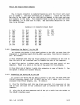
Sheet
o-System
Block
Diagram
When
the
system
is
initially
turned
on
the
RESEI'
block
(sheet
4)
pulls
the
POe
line
low
to
let
the
system
know
that
a
reset
condition
exists.
When
the
system
has
already
been
in
an on
comition,
the
PRESEI'
line
going
low
will
also
cause
it
to
issue
the
POe
signal.
01
board,
a
reset
condition
will
cause
the
processor
to
go
through
a
reset.
It
also
causes
Matx>ry
Control
to
issue
a
Pbantan.
When
the
MEMORY
OONI'ROL
block
(sheet
4)
is
given
a
RESET
it
issues
the
Phantom
signal
whim
disables
all
nenory
on
the
5-100
bus.
If
enabled,
the
block
will
cause
the
first
three
bytes
of
the
on-board
PRCM
to
be
addressed.
l>bnnally,
these
first
three
bytes
are
a jump
to
instruction
whim
causes
the
rest
of
the
nonitor
program
to
be
run.
Durin;J
normal
cperation,
the
memory
control
block
reads
the
address
lines
durin;J
an
address
cycle
to
determine
whether
any
of
the
on
board
PRCM
or
RAM
is
being
addressed.
The
jumpers
in
this
seciton
permit
the
use
of
lK,
2K
or
4K
EPRCM.
The
MEMORY
block
(sheet
5)
contains
the
on-board
PROM
and
RAM.
It
is
controlled
fran
menory
control,
the
5-100
system
control
bus
(via
the
S-lOO
interface
block)
or
the
CPU.
The
CLOCKS
and
CL<XI<
DRIVERS
blocks
(sheet
6)
generate
the
timing
signals
required
by
the
CPU
and
the
system.
The
clock
can
supply
a
4MHz
or
a
2MHz
clocking
signal,
jumper
selectable.
Even thoogh
not
necessary
with
the
Z-80
microprocessor,
a
phase
2
clock
signal
is
generated
to
maintain
compatabili
ty
with
S-lOO equipm:mt
designed
to
be
used
with
the
8080. The
clocks
block
also
supplies
the
base
signals
(2MCLK
and
SERCLK)
which
are
divided
down
to
supply
all
RS-232 baud
rates.
The
PRCCESSOR
block
(sheet
1)
is
the
heart
or,
nore
properly,
the
brain
of
the
entire
microcomputer
system.
It
regulates
all
processes,
addressing,
inputs
and
outputs.
en
bJard
all
address
and
data
signals
are
sent
over
r-t)S
level
data
and
address
buses.
All
off
board
addressing
and
data
communication
is
done
via
the
5-100
interface
block.
S-lOO
INTERFACE
block
and
the
CONTROL
SIGNAL
BUFFERS
block
(sheet
8)
consist
of
a
lll..1lYber
of
gates
which
take
processor
signals
and
convert
them
to
system
signals.
That
is,
many
of
the
signals
required
by
the
system
are
not
generated
directly
fran
the
Z-80.
The
signals
required
by
the
system
that
are
not
available
directly
are
synthesized
by
the
2CB
board.
The
Rev.
I-B
6/11/80
3-1