SERIES 22H Line Regen AC Flux Vector Control Installation & Operating Manual 3/05 MN722
Table of Contents Section 1 Quick Start Guide . . . . . . . . . . . . . . . . . . . . . . . . . . . . . . . . . . . . . . . . . . . . . . . . . . . . . . . . . . . . . . . . . . . . . . . . . . . . . . . . . 1-1 Overview . . . . . . . . . . . . . . . . . . . . . . . . . . . . . . . . . . . . . . . . . . . . . . . . . . . . . . . . . . . . . . . . . . . . . . . . . . . . . . . . . . . . . 1-1 Quick Start Checklist . . . . . . . . . . . . . . . . . . . . . . . . . . . . . . . . . . . . . . . . . . . . . .
Control Circuit Connections . . . . . . . . . . . . . . . . . . . . . . . . . . . . . . . . . . . . . . . . . . . . . . . . . . . . . . . . . . . . . . . . . . . . . 3-21 Converting Control Board Connections . . . . . . . . . . . . . . . . . . . . . . . . . . . . . . . . . . . . . . . . . . . . . . . . . . . . . . . 3-21 Inverter Control Board Connections . . . . . . . . . . . . . . . . . . . . . . . . . . . . . . . . . . . . . . . . . . . . . . . . . . . . . . . . . . 3-22 Serial Mode . . . . . . . .
Section 5 Troubleshooting . . . . . . . . . . . . . . . . . . . . . . . . . . . . . . . . . . . . . . . . . . . . . . . . . . . . . . . . . . . . . . . . . . . . . . . . . . . . . . . . . . 5-1 No Keypad Display - Display Contrast Adjustment . . . . . . . . . . . . . . . . . . . . . . . . . . . . . . . . . . . . . . . . . . . . . . . . . . 5-1 When a Fault is Displayed . . . . . . . . . . . . . . . . . . . . . . . . . . . . . . . . . . . . . . . . . . . . . . . . . . . . . . . . . . . . . . . . . . . .
Section 7 Specifications, Ratings & Dimensions . . . . . . . . . . . . . . . . . . . . . . . . . . . . . . . . . . . . . . . . . . . . . . . . . . . . . . . . . . . . . . 7-1 Specifications . . . . . . . . . . . . . . . . . . . . . . . . . . . . . . . . . . . . . . . . . . . . . . . . . . . . . . . . . . . . . . . . . . . . . . . . . . . . . . . . . 7-1 Operating Conditions . . . . . . . . . . . . . . . . . . . . . . . . . . . . . . . . . . . . . . . . . . . . . . . . . . . . . . . . . . . . . . . . . .
Section 1 Quick Start Guide Overview Quick Start Checklist If you are an experienced user of Baldor controls, you are probably already familiar with the keypad programming and keypad operation methods. If so, this quick start guide has been prepared for you. This procedure will help get your system up and running in the keypad mode quickly. This will allow motor and control operation to be verified.
Section 1 General Information Quick Start Procedure Initial Conditions Be sure the 22H control and motor are installed and wired according to the procedures in Section 3 of this manual. Become familiar with the keypad programming and keypad operation of the control as described in Section 4 of this manual. 1. Disconnect the load (including coupling or inertia wheels) from the motor shaft if possible. 2. Verify that all enable inputs to J1-8 are open. 3. Turn power on. Be sure no errors are displayed.
Section 2 General Information Overview The Baldor Series 22H Line Regen Vector Control provides full motoring and line regeneration to the AC power mains with a near unity power factor. The control uses PWM controlled by IGBT power transistors in both the converter and inverter sections of the control to provide 3 phase power to the motor and Regen power to the line.
Limited Warranty For a period of two (2) years from the date of original purchase, BALDOR will repair or replace without charge controls and accessories which our examination proves to be defective in material or workmanship. This warranty is valid if the unit has not been tampered with by unauthorized persons, misused, abused, or improperly installed and has been used in accordance with the instructions and/or ratings supplied.
Safety Notice This equipment contains voltages that may be as high as 1000 volts! Electrical shock can cause serious or fatal injury. Only qualified personnel should attempt the start−up procedure or troubleshoot this equipment. This equipment may be connected to other machines that have rotating parts or parts that are driven by this equipment. Improper use can cause serious or fatal injury. Only qualified personnel should attempt the start−up procedure or troubleshoot this equipment.
Section 1 General Information 2-4 General Information Caution: Suitable for use on a circuit capable of delivering not more than the RMS symmetrical short circuit amperes listed here at rated voltage. Horsepower RMS Symmetrical Amperes 1−50 5,000 51−200 10,000 201−400 18,000 401−600 30,000 601−900 42,000 Caution: Disconnect motor leads (T1, T2 and T3) from control before you perform a “Megger” test on the motor.
Section 3 Receiving & Installation Receiving & Inspection Physical Location The Series 22H Vector Control is thoroughly tested at the factory and carefully packaged for shipment. When you receive your control, there are several things you should do immediately. 1. Observe the condition of the shipping container and report any damage immediately to the commercial carrier that delivered your control. 2.
Section 1 General Information , Table 3-1 lists the Watts Loss ratings for Series 22H controls. Table 3-1 Series 22H Watts Loss Ratings. CONTROL STD PWM CONV & INV Losses QUIET PWM CONV & INV Losses CONTROL FIXED Losses BOOST REG Loss At Full Load Line Reactor Loss At Full Load STD PWM Total Losses QUIET PWM Total Losses MODEL No. SIZE INPUT VAC (Watts) (Watts) (Watts) (Watts) Cat. No.
Section 1 General Information Control Installation The control must be securely fastened to the mounting surface. Use the four (4) mounting holes to fasten the control to the mounting surface or enclosure. Through the Wall Mounting Control sizes E and F are designed for panel or through the wall installation. To mount a control through the wall, an optional Through the Wall mounting kit must be purchased. These kits are: Description Kit No. V0083991 Size E control Through the Wall mounting kit.
Section 1 General Information Optional Remote Keypad Installation The keypad may be remotely mounted using the optional Baldor keypad extension cable. The keypad assembly (white - DC00005A-01; grey - DC00005A-02) comes complete with the screws and gasket required to mount it to an enclosure. When the keypad is properly mounted to a NEMA Type 4X indoor enclosure, it retains the Type 4X indoor rating.
Section 1 General Information Electrical Installation Interconnection wiring is required between the motor control, AC power source, motor, host control and any operator interface stations. Use only UL (cUL) listed closed loop connectors that are of appropriate size for wire gauge being used. Connectors are to be installed using crimp tool specified by the manufacturer of the connector. Only Class 1 wiring should be used.
Section 1 General Information Figure 3-2 Recommended System Grounding − EK Note: A boost regulator is required and provided with each model EK control. Note: A line reactor is required and must be ordered separately. AC Main Supply L1 L2 JOG LOCAL FWD DISP REV SHIFT STOP RESET PROG ENTER Series H Note: Wiring shown for clarity of grounding method only. Not representative of actual terminal block location.
Section 1 General Information Current Requirements The input current for each control is given in Table 3-2 and the short circuit requirements are given in Table 3-3. The control may be damaged if input current exceeds ratings.
Section 1 General Information Protection Devices Be sure a suitable input power protection device is installed. Use the recommended circuit breaker or fuses listed in Table 3-5 and 3-6. Input and output wire size is based on the use of copper conductor wire rated at 75 °C. The table is specified for NEMA B motors. Circuit Breaker: 3 phase, thermal magnetic.
Section 1 General Information Wire Size and Protection Devices Table 3-5 230VAC Controls (3 Phase) Wire Size and Protection Devices Control Rating Amps HP 3 0.75 4 1 7 2 10 3 16 5 22 7.5 28 10 42 15 54 20 68 25 80 30 104 40 130 50 145 60 192 75 Input Breaker (Amps) 7 7 15 15 20 30 40 60 70 90 100 150 175 200 250 Input Fuse (Amps) Fast Acting Time Delay 5 4 6 5 12 9 15 12 25 20 35 30 45 35 70 60 80 70 100 90 125 110 175 150 200 175 225 200 300 250 Wire Gauge AWG mm2 14 2.5 14 2.5 14 2.5 14 2.5 12 3.
Section 1 General Information Three Phase Input Power Connections AC power and motor connections are different for controls that have a model number suffix of “EL” and “EK”. Be sure to use the correct procedure for your control. Note: “EK” Controls are input phase sensitive. Be sure all connections are correct. “EL” suffix The AC power and motor connections are shown in Figure 3-3. Overloads are not required. The 22H control has an electronic I2t motor overload protection.
Section 1 General Information “EK” suffix (“EK” Controls are input phase sensitive. Check all connections). The AC power and motor connections are shown in Figure 3-4. Overloads are not required. The 22H control has an electronic I2t motor overload protection. If motor overloads are desired, they should be sized according to the manufacturers specifications and installed between the motor and the T1, T2 and T3 terminals of the control. 1.
Section 1 General Information Single Phase Operation Single phase operation is not possible for Series 22H Line Regen Vector Controls. Operating the Control at a Reduced Input Voltage Series 22H Controls use a DC Bus regulation technique that provides full output voltage (240VAC for 230VAC Controls; or 480VAC for 460VAC controls) for the full input voltage range. However, at reduced input voltages the output current of the control may have to be derated.
Section 1 General Information Control Sizes C+, D, D+ Figure 3-1 Control and Contactor Transformer Locations Control Size Control Size E F Contactor Transformer Input Contactor Control Transformer Logic Control Board Input Contactor Control Transformer Control Size G+ Fuse Block xfmr Contactor Transformer Control Transformer Fan Transformers xfmr Swing out panel Contactor Transformer Input Contactor Not drawn to scale or proportion Size C+, D, D+ E, and F size control procedure: Control Tran
Figure 3-2 Configuring the Control Transformer for 380 - 400 VAC Installation Contactor Transformer Only size E and F controls require a change of the contactor transformer tap. See Figure 3-3. Use the taps (H1 to H5) that are correct for the input voltage.
Section 1 General Information Motor Connections Motor connections are shown in Figure 3-5. Figure 3-5 Motor Connections Notes: 1. Metal conduit should be used. Connect conduits so the use of Load Reactor or RC Device does not interrupt EMI/RFI shielding. Baldor Series 22H Control T1 T2 2. See Line/Load Reactors described previously in this section. 3. Use same gauge wire for Earth ground as for L1, L2 and L3.
Section 1 General Information Encoder Installation Electrical isolation of the encoder shaft and housing from the motor is required. Electrical isolation prevents capacitive coupling of motor noise that will corrupt the encoder signals. Baldor provides shielded wire for encoder connection. Figure 3-7 shows the electrical connections between the encoder and the encoder connector. Figure 3-8 shows the connections between the encoder connector and J1 of the control.
Section 1 General Information Home (Orient) Switch Input The Home or Orient function is active in the Bipolar and Serial modes and causes the motor shaft to rotate to a predefined home position. The homing function allows shaft rotation in the drive forward direction only. The home position is located when a machine mounted switch or the encoder “Index” pulse is activated (closed). Home is defined by a rising signal edge at terminal J1-27.
Control Board Jumpers Converter Section Control Board Figure 3-11 Converter Control Board Jumper JP1 Location Expansion Board Motor Control Board Keypad Connector 321 JP1 See recommended terminal tightening torques in Section 7. Table 3-9 Converter Control Board Jumper Jumper JP1 Jumper Position 1−2 2−3 Description of Jumper Position Setting Voltage Speed Command Signal. (Factory Setting) 4−20mA Speed Command Signal.
Section 1 General Information Analog Inputs Two analog inputs are available: analog input #1 (J1-1 and J1-2) and analog input #2 (J1-4 and J1-5) as shown in Figure 3-13. Either analog input may be selected in the Level 1 INPUT block, Command Select parameter value. Analog input #1 is selected if the parameter value is “Potentiometer”. Analog input #2 is selected if the parameter value is “+/-10Volts, +/-5 Volts or 4-20mA”. Figure 3-14 shows the equivalent circuits of the Analog Inputs.
Section 1 General Information Figure 3-14 Analog Inputs Equivalent Circuits J1 30KW 5.1V Zener -15VDC Notes: .033 mF 1 + − 5KW Analog Ground is separated from Chassis Ground. Electrically they are separated by an RC network. 20KW 2 − To Microprocessor + See recommended terminal tightening torques in Section 7. 1.
Section 1 General Information Control Circuit Connections There are two control boards in a Series 22H Vector Control. The Converter Control Board is used to rectify and process the incoming power. The Inverter Control Board provides the inverting and power output functions. The keypad is normally connected to the Inverter Control Board. Each converter board has its own J1 terminal strip. The Inverter Control Board provides the user interface for most external connections.
Section 1 General Information Inverter Control Board Connections Ten operating modes are available in the Series 22H vector control. These operating modes define the basic motor control setup and the operation of the input and output terminals. After the circuit connections are completed, the operating mode is selected by programming the Level 1 Input block, Operating Mode parameter.
Section 1 General Information Keypad Mode Connections The Keypad operating mode allows the control to be operated from the keypad. This mode requires no connections to J1. However, the Enable, Stop and External Trip inputs may optionally be used. All other opto inputs remain inactive. The analog outputs and opto-outputs remain active at all times. See Figure 3-18. Parameter Selection For operation in Keypad mode, set the Level 1 Input block, Operating Mode parameter to Keypad.
Section 1 General Information Standard Run 3 Wire Mode Connections In Standard Run mode, the control is operated by the opto isolated inputs at J1-8 through J1-16 and the analog command input. The opto inputs can be switches as shown in Figure 3-19 or logic signals from another device. The external trip opto input at J1-16 is active if connected as shown and the Level 2 Protection block, External Trip parameter is set to ON. For 4−20mA operation, refer to Table 3-10.
Section 1 General Information 15 Speed 2-Wire Mode Connections Switch Truth Table is defined in Table 3-11. Operation in the 15 Speed 2-Wire mode is controlled by the Opto Isolated inputs at J1-8 through J1-16. The Opto inputs can be switches as shown in Figure 3-20 or logic signals from another device. Switched inputs at J1-11 through J1-14 allow selection of 15 preset speeds and provide Fault Reset as defined in Table 3-11.
Section 1 General Information 3 Speed Analog 2 Wire Operating Mode Allows selection of 3 preset speeds with 2 wire inputs. The opto inputs can be switches as shown in Figure 3-21 or logic signals from another device. The values of the preset speeds are set in the Level 1 Preset Speeds block, Preset Speed #1, Preset Speed #2 and Preset Speed #3. Figure 3-21 3 SPD ANA 2 Wire Control Connection Diagram J1-8 CLOSED allows normal operation. OPEN disables the control and the motor coasts to a stop.
Section 1 General Information 3 Speed Analog 3 Wire Operating Mode Allows selection of 3 preset speeds with 3 wire inputs. The opto inputs can be switches as shown in Figure 3-22 or logic signals from another device. The values of the preset speeds are set in the Level 1 Preset Speeds block, Preset Speed #1, Preset Speed #2 and Preset Speed #3. Figure 3-22 3 SPD ANA 3 Wire Control Connection Diagram J1-8 CLOSED allows normal operation. OPEN disables the control and the motor coasts to a stop.
Section 1 General Information Bipolar Speed and Torque Mode Connections Provides bipolar speed or torque control. Also, you may store up to four (4) complete sets of operating parameters. This is important if you wish to store and use different acceleration rates, speed commands, jog speeds or to store tuning parameter values for different motors etc. The opto inputs can be switches as shown in Figure 3-23 or logic signals from another device.
Section 1 General Information Multiple Parameter Sets The following procedure allows you to program up to four complete sets of parameter values and to use these multiple parameter sets. When programming each parameter set, use the ENTER key to accept and automatically save parameter values. Note: The control can be programmed in the REMOTE mode with the drive enabled. The control must be disabled to change the operating mode parameter and the operating mode can not be stored in a parameter table. 1.
Section 1 General Information Process Mode Connections The process control mode provides an auxiliary closed loop general purpose PID set point control. The process control loop may be configured in various ways and detailed descriptions of the process mode are given in MN707 “Introduction to Process Control”. The opto inputs can be switches as shown in Figure 3-24 or logic signals from another device. Figure 3-24 Process Mode Connection Diagram J1-8 CLOSED allows normal operation.
Section 1 General Information Electronic Pot 2 Wire Operating Mode Provides speed Increase and Decrease inputs to allow EPOT operation with 2 wire inputs. The opto inputs can be switches as shown in Figure 3-25 or logic signals from another device. The values of the preset speeds are set in the Level 1 Preset Speeds block, Preset Speed #1 or Preset Speed #2. Figure 3-25 EPOT, 2 Wire Control Connection Diagram J1-8 CLOSED allows normal operation. OPEN disables the control and motor coasts to a stop.
Section 1 General Information Electronic Pot 3 Wire Control Mode Provides speed Increase and Decrease inputs to allow EPOT operation with 3 wire inputs. The opto inputs can be switches as shown in Figure 3-26 or logic signals from another device. Figure 3-26 EPOT, 3 Wire Control Connection Diagram J1-8 J1 CLOSED allows normal operation. OPEN disables the control and motor coasts to a stop. J1-9 Momentary CLOSED starts motor operation in the Forward direction.
Section 1 General Information External Trip Input To activate the External Trip input, the External Trip parameter in the programming Protection Block must be set to “ON”. Terminal J1-16 is available for connection to a normally closed thermostat or overload relay in all operating modes as shown in Figure 3-27. The thermostat or overload relay should be a dry contact type with no power available from the contact.
Section 1 General Information Figure 3-29 Opto-Input Equivalent Circuit (Using External Supply) Opto In #1 Opto In #2 Opto In #3 Opto In #4 Opto In #5 Opto In #6 Opto In #7 Opto In #8 Opto In #9 J1 Opto In #1 8 Opto In #2 9 Opto In #3 10 Opto In #4 11 Opto In #5 12 Opto In #6 13 Opto In #7 14 Opto In #8 15 Opto In #9 16 17 * User VCC (-) Opto Inputs Closing to Ground Opto-Isolated Outputs 9 10 11 See recommended terminal tightening torques in Section 7.
Section 1 General Information Figure 3-31 Opto-Output Equivalent Circuit J1 18 19 20 21 22 PC865 50mA max PC865 50mA max PC865 50mA max 41 42 43 Pre-Operation Checklist Opto Output 2 Opto Output 3 Opto Output 4 10 − 30VDC Opto Outputs PC865 50mA max See recommended terminal tightening torques in Section 7.
Section 1 General Information Power-Up Procedure This procedure will help get your system up and running in the Keypad mode quickly. This will allow you to prove the motor and control operation. This procedure assumes that the control and motor are correctly installed (see Section 3 for procedures) and that you have an understanding of the keypad programming & operation procedures. It is not necessary to wire the terminal strip to operate the motor in the Keypad mode.
Section 4 Programming and Operation Overview The Series 22H Vector Line Regen Control has two control boards installed. The “Converter Control Board” is used to rectify and process the incoming power. The “Inverter Control Board” provides the inverting and power output functions. Each control board has its own J1 terminal strip. The Inverter Control Board normally has the keypad connected to it.
Section 1 General Information Baldor Keypad The keypad is used to program the control parameters, operate the motor and monitor the status and outputs of the control by accessing the display options, diagnostic menus and the fault log. Figure 4-1 Keypad JOG FWD REV STOP - (Green) lights when Jog is active. (Green) lights when FWD direction is commanded. (Green) lights when REV direction is commanded. (Red) lights when motor STOP is commanded.
Section 1 General Information Display Mode The control is in the DISPLAY MODE at all times except when parameter values are changed (Programming mode). The Keypad Display shows the status of the control as in the following example. Motor Status Control Operation Output Condition Value and Units The DISPLAY MODE is used to view operating status, Diagnostic INFO and the Fault Log. The description of how to do these tasks are described on the following pages.
Section 1 General Information Display Mode Continued Display Screens & Diagnostic Information Access Action Description Display Comments Apply Power Logo display for 5 seconds. Display mode showing motor speed. No faults present. Local keypad mode. If in remote/serial mode, press local for this display. Diagnostic Access screen. Press DISP key 6 times Scroll to Diagnostic Information screen Press ENTER key Access diagnostic information. Press DISP key Display mode showing control temperature.
Section 1 General Information Display Mode Continued Fault Log Access Action When a fault condition occurs, motor operation stops and a fault code is displayed on the Keypad display. The control keeps a log of up to the last 31 faults. If more than 31 faults have occurred the oldest fault will be deleted from the fault log to make room for the newest fault. To access the fault log perform the following procedure: Description Apply Power Display Comments Logo display for 5 seconds.
Section 1 General Information Program Mode The Program Mode is used to: 1. Enter motor data. 2. CALC Presets and Autotune the drive. 3. Customize the drive (Control and Motor) parameters to your application. From the Display Mode press the PROG key to access the Program Mode. Note: When a parameter is selected, alternately pressing the Disp and Prog keys will toggle between the Display Mode and the selected parameter.
Section 1 General Information Program Mode Continued Changing Parameter Values when Security Code Not Used Use the following procedure to program or change a parameter already programmed into the control when a security code is not being used. The example shown changes the operating mode from Keypad to Bipolar. Action Apply Power Description Display Comments Keypad Display shows this opening message. Logo display for 5 seconds. If no faults and programmed for LOCAL operation. Display mode.
Section 1 General Information Program Mode Continued Reset Parameters to Factory Settings Sometimes it is necessary to restore the parameter values to the factory settings. Follow this procedure to do so. Be sure to change the Level 2 Motor Data block “Motor Rated Amps” to the correct value after this procedure (restored factory setting is 999). Note: All specific application parameters already programmed will be lost when resetting the control to factory settings.
Section 1 General Information Program Mode Continued Initialize New Firmware After new firmware is installed, the control must be initialized to the new firmware version and memory locations. Use the following procedure to Initialize the firmware. Action Apply Power Description Logo display for 5 seconds. If no faults and programmed for LOCAL operation. Display mode. Stop LED on. Enter program mode. Press or Scroll to Level 2 Blocks. Press ENTER key Select Level 2 Blocks.
Section 1 General Information Parameter Definitions Converter Control Board Parameters Converter section parameters are programmed at the factory. Table 4-1 is a list of the parameters that can be changed. However, to make any parameter adjustments the keypad must be installed in the Converter Control Board as described previously in this section. Each Converter section parameter is defined in Table 4-2.
Section 1 General Information Table 4-2 Converter Control Board Parameter Definitions Block Title Parameter Description MISC Factory Settings Restores factory settings for converter section parameters. Select YES and press ENTER to restore factory parameter values. The Keypad Display will show “Operation Done” then return to “NO” when complete. Line Inductor (Boost Regulator) The value of the internal or external boost regulator inductor in “mH”.
Section 1 General Information Inverter Control Board Parameters (Version 3.20) To make programming easier, parameters have been arranged into the two level structure shown in Table 4-3. Press the PROG key to enter the programming mode and the “Preset Speeds” programming block will be displayed. Use the Up ( ) and Down ( ) arrows to scroll through the parameter blocks. Press ENTER to access parameters within a programing block. Tables 4-4 and 4-5 provide an explanation of each parameter.
Section 1 General Information Table 4-4 Inverter Control Board Level 1 Parameter Definitions Block Title Parameter PRESET SPEEDS Description Preset Speeds #1 − #15 ACCEL/DECEL RATE Allows selection of 15 predefined motor operating speeds. Each speed may be selected using external switches connected to J1-11, J1-12, J1-13 and J1-14 when Operating Mode is set to 15 Speed. For motor operation, a motor direction command must be given along with a preset speed command.
Section 1 General Information Table 4-4 Inverter Control Board Level 1 Parameter Definitions - Continued Block Title Parameter Description KEYPAD SETUP Keypad Stop Key Stop Key - Keypad Stop Mode Stop Mode - Selects if the Stop command causes the motor to “COAST” to a stop or “REGEN” to a stop. In COAST, the motor is turned off and allowed to coast to a stop. In REGEN, the voltage and frequency to the motor is reduced at a rate set by “Decel Time”.
Section 1 General Information Table 4-4 Inverter Control Board Level 1 Parameter Definitions - Continued Block Title Parameter Description OUTPUT OPTO OUTPUT #1 − #4 Four optically isolated digital outputs that have two operating states, logical High or Low. Each output may be configured to any of the following conditions: Condition Description Ready Active when power is applied and no faults are present.
Section 1 General Information Table 4-4 Inverter Control Board Level 1 Parameter Definitions - Continued Block Title Parameter Description OUTPUT (Continued) Analog Output #1 and #2 Two Analog 0-5VDC linear outputs may be configured to represent any of 19 conditions as follows: Condition Description ABS Speed - Represents the absolute motor speed where 0VDC = 0 RPM and +5VDC = MAX RPM. ABS Torque - Represents the absolute value of torque where +5VDC = Torque at CURRENT LIMIT.
Section 1 General Information Table 4-4 Inverter Control Board Level 1 Parameter Definitions - Continued Block Title Parameter VECTOR CONTROL CTRL BASE Speed Sets the speed in RPM at which the saturation voltage of the control is reached. Above this RPM value the control will output constant voltage and variable frequency. LEVEL 2 BLOCK MN722 Description Feedback Filter A larger value provides a more filtered signal but at the cost of reduced bandwidth.
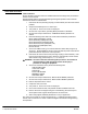
Section 1 General Information Table 4-5 Inverter Control Board Level 2 Parameter Definitions Block Title Parameter Description OUTPUT LIMITS Operating Zone Sets the PWM operating zone to Standard 2.5KHz or Quiet 8.0KHz output carrier frequency. Two operating modes are also selectable: Constant Torque and Variable Torque. Constant Torque allows 170 - 200% for 3 seconds overload or 150% for 60 seconds overload. Variable Torque allows 115% peak overload for 60 seconds.
Section 1 General Information OUTPUT FREQUENCY Figure 4-3 Maximum Output Frequency vs PWM Frequency It is recommended that the PWM frequency parameter be set to approximately16 times the maximum output frequency of the control. The greater the ratio, the more sinusoidal the output current waveform will be.
Section 1 General Information Table 4-5 Inverter Control Board Level 2 Parameter Definitions - Continued Block Title Parameter Description SECURITY CONTROL Security State Off - No security Access Code required to change parameter values. Local - Requires security Access Code to be entered (using the keypad) before parameter changes can be made using the Keypad. Serial - Requires security Access Code to be entered (over the Serial Link) before parameter changes can be made using the Serial Link.
Section 1 General Information Table 4-5 Inverter Control Board Level 2 Parameter Definitions - Continued Block Title Parameter Description BRAKE ADJUST Resistor Ohms The dynamic braking resistor value in ohms. Refer to dynamic braking manual or call Baldor for additional information. Resistor Watts The dynamic braking resistor watts rating. Refer to dynamic braking manual or call Baldor for additional information. The amount of DC injection brake current.
Section 1 General Information Table 4-5 Inverter Control Board Level 2 Parameter Definitions - Continued Block Title Parameter AUTO TUNING CALC Presets CMD Offset Trim CUR Loop COMP Flux CUR Setting Feedback Tests Slip FREQ Test SPD CNTRLR CALC LEVEL 1 BLOCK 4-22 Programming & Operation Description The Auto Tune procedure is used to automatically measure and calculate certain parameter values. Dynamic Brake Hardware is required to perform “Slip Freq Test” and “Spd Cntrlr Calc” autotuning test.
Section 5 Troubleshooting Baldor Series 22H Controls require very little maintenance and should provide years of trouble free operation when installed and applied correctly. Occasional visual inspection should be considered to ensure tight wiring connections and to avoid the build up of any dust, dirt, or foreign debris which can reduce heat dissipation. The control should be mounted in a location that protects the internal circuits and external wiring from moisture or liquid contaminants.
Section 1 General Information Table 5-1 Converter Control Board Fault Messages FAULT MESSAGE DESCRIPTION Current Sens FLT Defective phase current sensor or open circuit detected between control board and current sensor. DC Bus High Bus over voltage condition occurred. DC Bus Low Bus under voltage condition occurred. GND FLT Low impedance path detected between an output phase and ground.
Section 1 General Information Table 5-2 Inverter Control Board Fault Messages FAULT MESSAGE DESCRIPTION Current Sens FLT Defective phase current sensor or open circuit detected between control board and current sensor. DC Bus High Bus over voltage condition occurred. DC Bus Low Bus under voltage condition occurred. Encoder Loss Encoder coupling slipping or broken; noise on encoder lines, encoder power supply loss or defective encoder.
Section 1 General Information How to Access the Fault Log When a fault condition occurs, motor operation stops and a fault code is displayed on the keypad display. The control keeps a log of up to the last 31 faults. If more than 31 faults have occurred the oldest fault will be deleted from the fault log to make room for the newest fault. To access the fault log use the following procedure: Action Description Apply Power Display Comments Logo display for 5 seconds.
Section 1 General Information How to Clear the Fault Log Use the following procedure to clear the fault log and reset the internal clock. Action Description Apply Power Display Comments Logo display for 5 seconds. Display mode showing output frequency. Display mode. Press DISP key Press DISP to scroll to the Fault Log entry point. Press ENTER key Displays most recent message. 1=Most recent fault. 2=Second most recent fault, etc. Press ENTER key Fault log is cleared. No faults in fault log.
Section 1 General Information How to Access Diagnostic Information Action Description Display Comments Apply Power Logo display for 5 seconds. Display mode showing motor speed. No faults present. Local keypad mode. In remote/serial mode, disable drive then press local for this display. Press DISP key 6 times Scroll to Diagnostic Information screen Diagnostic Access screen. Press ENTER key Access diagnostic information. First Diagnostic Information screen.
Section 1 General Information Table 5-3 Converter Section Troubleshooting INDICATION POSSIBLE CAUSE CORRECTIVE ACTION Current Sense FLT Open circuit between control board and current sensor or defective current sensor. Check control wires between control board and current feedback sensor. DC Bus High Incorrect setting of converter bridge parameter. Check Bus Capacitance value of converter section parameters. Decel rate too fast. Increase Decel time parameter setting.
Section 1 General Information Table 5-3 Converter Section Troubleshooting Continued INDICATION Over Current FLT POSSIBLE CAUSE CORRECTIVE ACTION Possible converter transistor failure. Check transistors for shorted junctions. Incorrect inductance set in Line Inductor parameter. Check inductance parameter value. Overload FLT Drive overloaded. Verify proper sizing of control and motor. PWR Base FLT Incorrect phase connections.
Section 1 General Information Table 5-4 Inverter Section Troubleshooting INDICATION No Display POSSIBLE CAUSE CORRECTIVE ACTION Lack of input voltage. Check input power for proper voltage. Verify fuses are good (or breaker is not tripped). Loose connections. Check input power termination. Verify connection of operator keypad. Bent pins in keypad to control connector. Check connector pins and straighten as required. Adjust display contrast. See Adjust Display Contrast in Sec. 4. Encoder miswired.
Section 1 General Information Table 5-4 Inverter Section Troubleshooting INDICATION External Trip POSSIBLE CAUSE Continued CORRECTIVE ACTION Motor ventilation insufficient. Clean motor air intake and exhaust. Check external blower for operation. Verify motor’s internal fan is coupled securely. Verify correct line power to external blower. Motor draws excessive current. Check motor for overloading. Verify proper sizing of control and motor. No thermostat connected. Connect thermostat.
Section 1 General Information Table 5-4 Inverter Section Troubleshooting Continued INDICATION POSSIBLE CAUSE Motor has wrong response to Speed Command Analog input common mode voltage may be excessive. Connect control input source common to control common to minimize common mode voltage. Maximum common mode voltage at terminals J1-4 and J1-5 is ±15VDC referenced to chassis common. Incorrect MIN or MAX speed settings.
Section 1 General Information Table 5-4 Inverter Section Troubleshooting INDICATION POSSIBLE CAUSE Continued CORRECTIVE ACTION New Base ID Software parameters are not initialized on newly installed control board. Press “RESET” key on keypad to clear the fault condition. Reset parameter values to factory settings. Access diagnostics and compare power base ID number to list in Table 5-5 to ensure a match. Re-enter the Parameter Block Values you recorded in the User Settings at the end of this manual.
Section 1 General Information Table 5-4 Inverter Section Troubleshooting INDICATION POSSIBLE CAUSE Continued CORRECTIVE ACTION Power Module Power supply failure. Press “RESET” key on keypad. If fault remains, call Baldor. PWR Base FLT Improper ground Be sure control has separate ground wire to earth ground. Panel grounding or conduit connections is not sufficient. Disconnect motor leads from control and retry test. If fault remains, call Baldor. Excessive current usage.
Section 1 General Information Table 5-5 Power Base ID - Series 22H 230VAC Catalog Numbers 460VAC Power Base ID No. Catalog Numbers Power Base ID No.
Section 1 General Information Electrical Noise Considerations All electronic devices are vulnerable to significant electronic interference signals (commonly called “Electrical Noise”). At the lowest level, noise can cause intermittent operating errors or faults. From a circuit standpoint, 5 or 10 millivolts of noise may cause detrimental operation. For example, analog speed and torque inputs are often scaled at 5 to 10 VDC maximum with a typical resolution of one part in 1,000.
Section 1 General Information Electrical Noise Considerations Special Drive Situations Continued For severe noise situations, it may be necessary to reduce transient voltages in the wires to the motor by adding load reactors. Load reactors are installed between the control and motor. Reactors are typically 3% reactance and are designed for the frequencies encountered in PWM drives.
Section 6 Manual Tuning the Series 22H Control Manually Tuning the Control In some applications the drive cannot be accurately auto-tuned in an application. In these cases it is necessary to calculate the values needed to tune the drive and manually enter these calculated parameter values. Motor Mag Amps Parameter This parameter is located in the Level 2, Motor Data Block. This parameter is normally entered using the nameplate data (motor no load amps) or auto−tuned.
Section 1 General Information Current Int Gain Parameter The Current Int Gain parameter located in the Level 1 Vector Control Block is factory preset at 150 Hz. This setting is suitable for essentially all systems. DO NOT CHANGE WITHOUT FACTORY APPROVAL. Speed Prop Gain Parameter The Speed Prop Gain parameter located in the Level 1 Vector Control Block is factory set to 10. This gain may be increased or decreased to suit the application.
Section 1 General Information PI Controller Both the current and rate control loops are of the Proportional plus Integral type. If “E” is defined to be the error signal, E = Command − Feedback then the PI controller operated on “E” as Output = (Kp * E) + (Ki s E dt) where Kp is the proportional gain of the system and Ki is the integral gain of the system. The transfer function (output /E) of the controller using 1/s (Laplace Operator) to denote the integral, Output/E = Kp + KI / s = Kp (s + Ki/Kp) /s.
Section 1 General Information 6-4 Manual Tuning the Series 22H Control MN722
Section 7 Specifications, Ratings & Dimensions Specifications: Horsepower Input Frequency Output Voltage Output Current Service Factor Duty Overload Capacity Speed Command Potentiometer 10-50 HP @ 230VAC 10-450 HP @ 460VAC 50/60 HZ ± 5% Note: 50Hz operation requires a 15% control derating. 0 to Maximum Input VAC See Ratings Table 1.0 Continuous Constant Torque Mode: 170-200% for 3 secs 150% for 60 secs Variable Torque Mode: 115% for 60 secs 5k or 10k ohm, 0.
Control Specifications: Control Method Velocity Loop Bandwidth Current Loop Bandwidth Maximum Output Frequency Standard Frequency Version Quiet Frequency Version Selectable Operating Modes PWM Adjustable to 180 Hz Adjustable to 1200 Hz 500 Hz Full rating 1-2.5 KHz PWM frequency, Adjustable to 5 KHz with linear derating (between 2.
Digital Inputs: Opto-isolated Logic Inputs Rated Voltage Input Impedance Leakage Current 9 Assignable 10 - 30 VDC (closed contacts std) 6.
Series 22H Vector Control Ratings CATALOG NO. INPUT VOLT ENCLOSURE SIZE STANDARD 2.5 kHz PWM CONSTANT TORQUE HP QUIET 8.0 kHz PWM VARIABLE TORQUE KW IC IP HP CONSTANT TORQUE VARIABLE TORQUE KW IC IP HP KW IC IP HP KW IC IP ZD22H210−EL 230 C+ 10 7.4 28 56 10 7.4 28 32 10 7.4 28 48 10 7.4 28 32 ZD22H215−EL 230 C+ 15 11.1 42 84 15 11.1 42 48 10 7.4 30 61 15 11.1 42 48 ZD22H220−EL 230 C+ 20 14.9 55 100 20 14.9 55 62 15 11.
Section 1 General Information Table 7-6 Matched Component Matrix Control Catalog No. Control Specification No. 230 VAC 3% Line Reactor Catalog No. 380-415 VAC 4% Line Reactor Catalog No. 460 VAC 3% Line Reactor Catalog No. Boost Regulator Specification No. FIlter Specification No.
Section 1 General Information Terminal Tightening Torque Specifications Table 7-7 Tightening Torque Specifications Tightening Torque Catalog No. Power TB1 Ground Control J1 Lb-in Nm Lb-in Nm Lb-in Nm ZD22H210−EL 35 4 50 5.6 7 0.8 ZD22H215−EL 35 4 50 5.6 7 0.8 ZD22H220−EL 35 4 50 5.6 7 0.8 ZD22H225−EL 35 4 50 5.6 7 0.8 ZD22H230−EL 35 4 50 5.6 7 0.8 ZD22H240−EL 35 4 50 5.6 7 0.8 ZD22H250−EL 35 4 50 5.6 7 0.8 ZD22H410−EL 35 4 50 5.6 7 0.
Section 1 General Information Dimensions Size C+ Control 0.40 (10.2) 12.20(309.9mm) 11.50 (292.1) 0.50 (12.7) 5.25 (133.3) 5.25 (133.3) AIR OUTLET AIR OUTLET JOG LOCAL FWD DISP REV SHIFT STOP RESET 12.00(304.8) 0.31 (7.9) LIFTING FLANGE AIR OUTLET PROG ENTER 28.32 (719.3) 29.25 (743.0) AIR INLET (Top) 30.00 (762.0) AIR OUTLET AIR OUTLET .31(7.9mm) AIR INLET (Bottom) Note: Allow 2 inches minimum clearance on all sides for ventilation.
Section 1 General Information Dimensions Continued Size D+ Control 0.40(10.2) 0.50 (12.7) 12.20(309.9) 14.50(368.3) 6.75 (171.5) 6.75 (171.5) AIR OUTLET AIR OUTLET JOG 12.00(304.8) 0.31 (7.9) LIFTING FLANGE AIR OUTLET LOCAL FWD DISP REV SHIFT STOP RESET PROG ENTER 36.00 (914.4) AIR INLET (Top) 35.25 (895.4) 34.08 (865.6) AIR OUTLET AIR OUTLET 0.31 (7.9) WIDE AIR INLET (Bottom) Note: Allow 2 inches minimum clearance on all sides for ventilation.
Section 1 General Information Dimensions Continued Size D Control 14.50 (368.5mm) Air Outlet 13.50 (343.0mm) 25.00 (635.0mm) JOG LOCAL FWD DISP REV SHIFT STOP RESET PROG ENTER 24.25 (616.0mm) 23.12 (587.0mm) .31 (8.0mm) CUSTOMER POWER CONNECTIONS AIR INLET 10.00 (254.0mm) 10.20 (259.
Section 1 General Information Dimensions Continued Size E Control Air Outlet Thru−wall Mounting Flange Surface Mounting Flange .38 (9.5mm) 2 Places R AM VO Hz JOG FWD REV LOCAL PROG DISP SHIFT ENTER STOP RESET 30.00 (762mm) .38 2 Places (9.5mm) 17.70 (450mm) 5.75 (146mm) 6.
Section 1 General Information Dimensions Continued Size E Control − Through−Wall Mounting Mounting hole locations for Thru-Wall or surface mounting. Recommended hardware: 5/16″ or M8. (4 Places) (716mm) (711mm) (686mm) (672mm) 27.00 26.44 (552mm) 21.75 (343mm) 13.50 (133mm) Mounting hole locations for Thru-Wall mounting using kit #0083991. Thru hole .218″ (5.5mm) DIA. (4 Places) 28.19 28.00 Cutout for thru−wall mounting 5.25 MN722 (425mm) 16.75 (430mm) 16.94 (445mm) 17.54 (394mm) 15.50 10.
Section 1 General Information Dimensions Continued Size E Control − Through−Wall Mounting Continued 14 Places Controller Assembly 4 Places Customer’s Panel Cut foam tape and apply to perimeter of opening (to seal installation of controller) Bracket 2 Places Bracket 2 Places Thru−Wall Mounting Kit No. V0083991 Parts List QTY Part No. Description 2 V1083991 Bracket, small (left & right) 2 V1083992 Bracket, Large (top & bottom) 14 V6300710 Screw, 10-32 x 5/8 14 V6420010 Lock Washer No.
Section 1 General Information Dimensions Continued Size F Control Thru−wall Mounting Flange 22.75 (577.9mm) .38 (9.5mm) 3 Places Surface Mounting Flange Air Outlet 45.00 (1143mm) 44.00 (1117.6mm) 11.38 (28.9mm) 0.38 (9.5mm) 3 Places 27.00 (686mm) MN722 11.38 (28.9mm) Air Inlet 6.76 (172mm) 6.
Section 1 General Information Dimensions Continued Size F Control − Through−Wall Mounting Mounting hole locations for Thru-Wall mounting or without thru-wall mounting kit #0084001. Thru hole .218″ (5.5mm) DIA. (16 Places, coded A) A B 43.01 42.24 41.98 40.74 B B A Mounting hole locations for Thru-Wall mounting using kit #0084001. Thru hole .218″ (5.5mm) DIA. (18 Places, coded B) A B B B 36.99 A A B B 30.86 A 28.99 A A A 20.99 Cutout for thru−wall mounting B B A A 12.99 B 11.
Section 1 General Information Dimensions Continued Size F Control − Through−Wall Mounting Continued 34 Places Controller Assembly Customer’s Panel Cut foam tape and apply to perimeter of cutout (to seal installation of controller) Bracket 2 Places Bracket 2 Places Thru−Wall Mounting Kit No. V0084001 Parts List QTY Part No. Description 2 V1084002 Bracket, small (left & right) 2 V1084001 Bracket, Large (top & bottom) 34 V6300710 Screw, 10-32 x 5/8 34 V6420010 Lock Washer No.
Section 1 General Information Dimensions Continued Size G+ Control 35.18 [893.6] 24.00 [609.6] 3.72 [94.6] Removable Conduit Mounting Plates (Customer Power COnnections) 8.63 [219] 8.63 [219] 12.41 [315] 2.66 [67.6] 63.00 [1600] 23.63 [600] Air Outlet Grills (2) LINE REGEN 93.00 [2362] Air Inlet Grills (8) 90.55 [2300] 4.00 [101.
Section 1 General Information Dimensions Continued Size H Control 35.18 [893.6] Removable Conduit Mounting Plates (Customer Power Connections) 24.00 [609.6] 3.72 [94.6] 8.63 [219] 12.41 8.63 [315] [219] 2.66 [67.6] 94.5 [2400] LINE REGEN 93.00 [2362] 90.55 [2300] 23.63 [600] Air Outlet Grills (3) Air Inlet Grills (12) 4.00 [101.
Section 1 General Information EK Controls - Filter Assembly A B E F D C G Dimension A B C D E F G 7-18 Specifications, Ratings & Dimensions LF1015 In mm 7.75 196.9 4.00 101.6 1.81 46.0 15.25 387.4 3.52 89.4 2.00 50.8 0.92 23.3 LF2015 In mm 10.25 260.3 5.00 127.0 3.31 84.1 18.00 457.2 3.65 92.7 2.00 50.8 0.92 23.
Section 1 General Information EK Controls - Boost Regulators H B STACK G C E Max D F 0.380 4 PLACES L1A L2A L3A I A MAX L1 X2 L3 X1 L2 X3 “HR” .13 HP 60 Electrical Specification/Approximate Weight Baldor P/N mH Amps Lbs V2080709 1.20 68 80 H I F D A 11.75 B 2.25 C 5.50 Dimensions - inches D E F 9.25 4.50 12.25 G 5.75 H 0.50 I 1.50 H 0.62 0.63 I 3.79 3.79 .44” DIA X .
Section 1 General Information EK Controls - Boost Regulators Continued I H .44” DIA X .75” LONG SLOT 4 PLACES F D L1A L2A L3A B STACK G C E MAX TERMINAL BLOCK To Control J3 Connector “HR” A MAX L1 L2 L3 X1 X2 X3 Electrical Specifications/Approximate Weight HP Baldor P/N mH Amps Lbs 150 V2080712 0.50 162 155 H I A 18.00 F D B 2.50 C 9.50 Dimensions - inches D E F 4.50 8.25 13.56 G 12.00 H 0.63 I 4.53 H 0.63 I 4.88 .44” DIA X .
Appendix A Converter Section Parameter Values Table A-1 Converter Section Parameter Block Values Level 1 Level 1 Blocks Block Title MISC Parameter FACTORY SETTINGS Adjustable Range NO, YES LINE INDUCTOR SECURITY CONTROL MN722 Factory Setting User Setting NO CALC BUS CAPACITANCE 50 − 500% 100% DAC SELECTION AB BC CROSS AB CROSS DQ CONTRLR DQ CURRENTS IQ COMMAND IB AND IC Va AND Vb Ia AND Ib AB BC CROSS SECURITY STATE OFF LOCAL SERIAL TOTAL OFF ACCESS TIMEOUT 0 − 600 SEC 0 SEC ACCESS COD
Section 1 General Information Power Output Section Parameter Values (Version 3.
Section 1 General Information Table A-2 Power Output Parameter Block Values Level 1 Continued Level 1 Blocks - Continued Block Title INPUT OUTPUT MN722 Parameter P# Adjustable Range Factory OPERATING MODE 1401 1− KEYPAD 2− STANDARD RUN 3− 15SPD 4− 3SPD ANA 2WIRE 5− 3SPD ANA 3WIRE 6− SERIAL 7− BIPOLAR 8− PROCESS MODE 9− EPOT −2WIRE 10− EPOT −3WIRE KEYPAD COMMAND SELECT 1402 0− POTENTIOMETER 1− +/-10 VOLTS 2− +/-5 VOLTS 3− 4 To 20 mA 4− 10V W/TORQ FF 5− EXB PULSE FOL 6− 5VOLT EXB 7− 10 VOLT EXB
Section 1 General Information Table A-2 Power Output Parameter Block Values Level 1 Continued Level 1 Blocks - Continued Block Title OUTPUT (Continued) VECTOR CONTROL Parameter P# ANALOG OUT #1 1508 ANALOG OUT #2 1509 ANALOG #1 SCALE ANALOG #2 SCALE Adjustable Range 0− ABS SPEED 1− ABS TORQUE 2− SPEED COMMAND 3− PWM VOLTAGE 4− FLUX CURRENT 5− CMD FLUX CUR 6− LOAD CURRENT 7− CMD LOAD CUR 8− MOTOR CURRENT 9− LOAD COMPONENT 10− QUAD VOLTAGE C VOLTAGE O G 11− DIRECT 12− AC C VOLTAGE O G 13− BUS VOLTA
Section 1 General Information Table A-3 Power Output Parameter Block Values Level 2 Level 2 Blocks Block Title OUTPUT LIMITS CUSTOM UNITS PROTECTION MISCELLANEOUS SECURITY CONTROL MOTOR DATA MN722 Parameter P# Adjustable Range Factory OPERATING ZONE 2001 1−STD CONST TQ 2−STD VAR TQ 3−QUIET CONST TQ 4−QUIET VAR TQ STD CONST TQ MIN OUTPUT SPEED 2002 0-MAX Speed RPM 0 RPM MAX OUTPUT SPEED 2003 0-30000 RPM Rated Motor Speed PK CURRENT LIMIT 2004 0-PEAK RATED CURRENT PK Control Rating
Section 1 General Information Table A-3 Power Output Parameter Block Values Level 2 Continued Level 2 Blocks - Continued Block Title Parameter P# Adjustable Range Factory BRAKE RESISTOR OHMS 2601 0-250.0 Ohms Factory Set ADJUST RESISTOR WATTS 2602 0-360.
Section 1 General Information Table A-3 Power Output Parameter Block Values Level 2 Continued Level 2 Blocks - Continued Block Title COMMUNICATIONS AUTO-TUNING Parameter P# Adjustable Range Factory PROTOCOL 2801 0−RS−232 ASCII, 1−RS-485 ASCII, 2−RS−232 BBP, 3−RS-485 BBP RS−232 BBP BAUD RATE 2802 0−9600, 1−19.2KB, 2−38.4KB, 3−57.6KB, 4−115.2KB, 5−230.4KB, 6−460.8KB, 7−921.
Section 1 General Information A-8 Appendix A MN722
Appendix B MN722 Appendix B-1
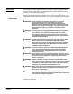
Section 1 General Information Remote Keypad Mounting Template 4.00 2.500 (A) (A) Four Places Tapped mounting holes, use #29 drill and 8-32 tap (Clearance mounting holes, use #19 or 0.166″ drill) 5.500 4.810 1-11/16″ diameter hole Use 1.25″ conduit knockout (B) 1.340 (A) (A) 1.250 B-2 Appendix B Note: Template may be distorted due to reproduction.
Baldor District Offices UNITED STATES ARIZONA PHOENIX 4211 S 43RD PLACE PHOENIX, AZ 85040 PHONE: 602−470−0407 FAX: 602−470−0464 CALIFORNIA LOS ANGELES 6480 FLOTILLA COMMERCE, CA 90040 PHONE: 323−724−6771 FAX: 323−721−5859 HAYWARD 21056 FORBES STREET HAYWARD, CA 94545 PHONE: 510−785−9900 FAX: 510−785−9910 COLORADO DENVER 2520 W BARBERRY PLACE DENVER, CO 80204 PHONE: 303−623−0127 FAX: 303−595−3772 FAX: 586−978−9969 MICHIGAN Continued GAND RAPIDS 668 3 MILE ROAD NW GRAND RAPIDS, MI 49504 PHONE: 616−785−1784 F
BALDOR ELECTRIC COMPANY P.O. Box 2400 Ft.
Series 22H Line Regenerative Vector Control MN722