Manual VN1600 Interface Family VN1610 / VN1611 / VN1630A / VN1640A Version 2.
Imprint Vector Informatik GmbH Ingersheimer Straße 24 D-70499 Stuttgart The information and data given in this user manual can be changed without prior notice. No part of this manual may be reproduced in any form or by any means without the written permission of the publisher, regardless of which method or which instruments, electronic or mechanical, are used. All technical information, drafts, etc. are liable to law of copyright protection. Copyright 2013, Vector Informatik GmbH. Printed in Germany.
Manual Contents Contents 1 Introduction 3 1.1 About this User Manual 1.1.1 Certification 1.1.2 Warranty 1.1.3 Registered trademarks 4 5 5 5 2 VN1600 Interface Family 6 2.1 Introduction 7 2.2 Accessories 7 2.3 Getting Started 2.3.1 Step 1: Driver Installation 2.3.2 Step 2: Device Installation 2.3.3 Step 3: Device Configuration 2.3.4 Step 4: Quick Test 8 8 8 8 9 2.4 VN1610 2.4.1 2.4.2 2.4.3 2.4.
Manual VN1600 Interface Family 3.1.1 3.1.2 3.1.3 Contents General Information Software Sync Hardware Sync 40 42 43 4 Driver Installation 44 4.1 Minimum Requirements 45 4.2 Hints 45 4.3 Vector Driver Setup 46 4.4 Vector Hardware Configuration 48 4.5 Loop Tests 4.5.1 CAN 4.5.2 FlexRay 4.5.3 MOST 4.5.4 Ethernet 50 50 53 54 54 © Vector Informatik GmbH Version 2.
Manual Introduction 1 Introduction In this chapter you find the following information: 1.1 About this User Manual Certification Warranty Registered trademarks © Vector Informatik GmbH page 4 Version 2.
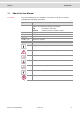
Manual 1.1 Introduction About this User Manual Conventions In the two following charts you will find the conventions used in the user manual regarding utilized spellings and symbols. Style Utilization bold Blocks, surface elements, window- and dialog names of the software. Accentuation of warnings and advices. [OK] Push buttons in brackets File|Save Notation for menus and menu entries Microsoft Legally protected proper names and side notes. Source Code File name and source code.
Manual Introduction 1.1.1 Certification Certified Quality Vector Informatik GmbH has ISO 9001:2008 certification. The ISO standard is a Management System globally recognized standard. 1.1.2 Warranty Restriction of warranty We reserve the right to change the contents of the documentation and the software without notice. Vector Informatik GmbH assumes no liability for correct contents or damages which are resulted from the usage of the documentation.
Manual VN1600 Interface Family 2 VN1600 Interface Family In this chapter you find the following information: 2.1 Introduction page 7 2.2 Accessories page 7 2.3 Getting Started page 8 2.4 VN1610 page 10 2.5 VN1611 page 12 2.6 VN1630 page 15 2.7 VN1630A page 27 2.8 VN1640 page 28 2.9 VN1640A page 38 © Vector Informatik GmbH Version 2.
Manual 2.1 VN1600 Interface Family Introduction General information The VN1600 interface family is an advanced development of the proven CANcaseXL which is a flexible and cost-efficient solution for CAN, LIN, K-Line or J1708 applications. An excellent performance with minimal latency times and high time stamp accuracy is also guaranteed. The multi-application functionality of the VN1600 interface family supports simultaneous operation of different applications on one channel, e. g. CANoe and CANape.
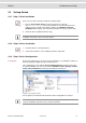
Manual 2.3 VN1600 Interface Family Getting Started 2.3.1 Step 1: Driver Installation Please use the drivers from the included Vector Driver Disk. 1. Execute Vector Driver Setup from the autostart menu or directly from \Drivers\Setup.exe before the VN16xx is connected to the PC over USB. If you have already connected the VN16xx, the Windows found new Hardware wizard appears. Close this wizard and then execute the driver setup. 2. Finish the driver installation with the setup.
Manual VN1600 Interface Family 2.3.4 Step 4: Quick Test Note: Please execute the test described in section Loop Tests on page 50. © Vector Informatik GmbH Version 2.
Manual 2.4 VN1600 Interface Family VN1610 2.4.1 Main Features VN1610 features The main features of the VN1610 interface are: > 2x CAN high-speed 1051cap transceivers (capacitively decoupled) > Software sync Figure 3: VN1610 CAN Interface. 2.4.2 Connectors > D-SUB9 (CH1/2) The VN1610 has a D-SUB9 connector with two CAN channels. Further information on the pin assignment for CH1/CH2 can be found in section Pin Assignment CH1 and CH2 on page 11.
Manual VN1600 Interface Family 2.4.3 Pin Assignment CH1 and CH2 D-SUB9 connector The pin assignment of the D-SUB9 connector (CH1 and CH2) is as follows: CH1/CH2 CAN Y cable Use the CANcable 2Y to access both channels on separate D-SUB9 connectors (see accessories manual, article number 05075). Figure 4: CANcable 2Y connected to VN1610. 2.4.4 Technical Data CAN channels 2x CAN high-speed 1051cap, up to 2 Mbit/s Temperature range Operating: -40 °C...+70 °C Shipping and storage: -40 °C...
Manual 2.5 VN1600 Interface Family VN1611 2.5.1 Main Features VN1611 features The main features of the VN1611 interface are: > 1x LIN 7269cap transceiver (capacitively decoupled) > 1x CAN high-speed 1051cap transceiver (capacitively decoupled) > Software sync Figure 5: VN1611 LIN/CAN Interface. Note: The VN1611 does not support LIN2.1 compliance tests. Please use the VN1630 or the VN1640 for these purposes. 2.5.
Manual VN1600 Interface Family 2.5.3 Pin Assignment CH1 and CH2 D-SUB9 connector The pin assignment of the D-SUB9 connector (CH1 and CH2) is as follows: CH1/CH2 Pdis: power disable CAN/LIN Y cable Use the CANcable 2Y to access both channels on separate D-SUB9 connectors (see accessories manual, article number 05075). Figure 6: CANcable 2Y connected to VN1611. Note: If pin 4 (Pdis) is connected to pin 3 (VB-), the internal power supply is disabled.
Manual VN1600 Interface Family 2.5.4 Technical Data CAN channels 1x CAN high-speed 1051cap, up to 2 Mbit/s LIN channels 1x LIN 7269cap, up to 330 kbit/s K-Line channels 1 Temperature range Operating: -40 °C...+70 °C Shipping and storage: -40 °C...+85 °C Relative humidity of ambient air 15 %...
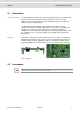
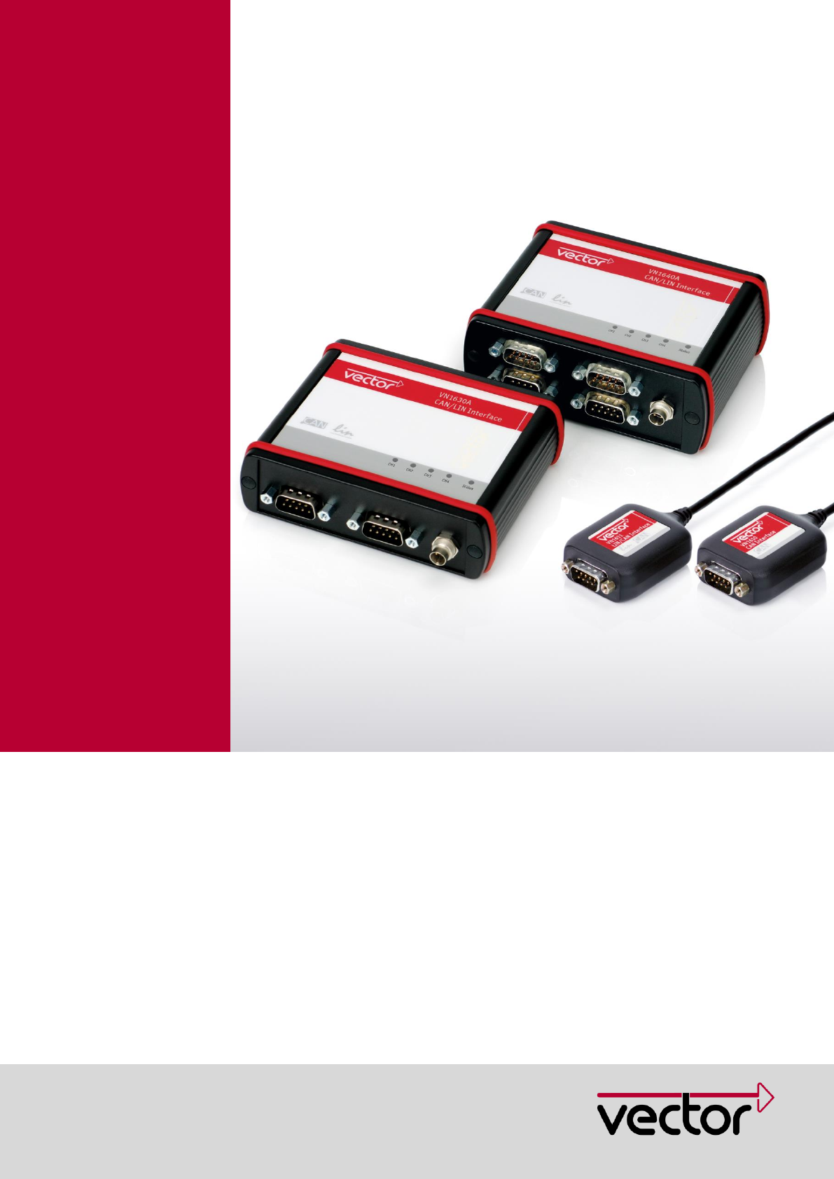
Manual 2.6 VN1600 Interface Family VN1630 2.6.1 Main Features VN1630 features The main features of the VN1630 interface are: > 2x CAN high-speed 1051cap transceivers (capacitively decoupled) > 2x additional plug-in locations for CAN/LINpiggies > Fifth channel for dedicated digital-analog input/output tasks > Software sync > Hardware sync (via SYNCcableXL) Figure 7: VN1630 CAN/LIN Interface. 2.6.2 Connectors Bus Side Device connectors Figure 8: VN1630 with 1x Sync and 2x D-SUB9.
Manual VN1600 Interface Family > D-SUB9 (CH1/3 and CH2/4) The VN1630 has two D-SUB9 connectors, each with up to two channels (CAN/CAN or LIN/CAN). Further information on the pin assignment for CH1/CH3 and CH2/CH4 can be found in section Pin Assignment CH1/3 and CH2/4 on page 18. 2.6.3 Connectors USB Side Device connectors Figure 9: VN1630 with 1x USB and 1x D-SUB9. > USB Connect your PC and the VN1630 over USB to install and to use the device with measurement applications (CANoe, CANalyzer).
Manual VN1600 Interface Family 2.6.4 Bus Configuration Piggybacks for CH1 and CH2 An advantage of the VN1630 is its two Piggyback plug-in locations (CH1 and CH2). Depending on requirements, electrically decoupled CAN High-Speed, CAN LowSpeed, CAN Single Wire, J1708 or LIN transceivers may be used. In addition, two electrically decoupled built-in CAN TJA1051 (high-speed) transceivers are available (CH3 and CH4). CH5 is reserved for dedicated IO tasks.
Manual VN1600 Interface Family 2.6.5 Pin Assignment CH1/3 and CH2/4 Double assignment of D-SUB9 connectors CH1 and CH2 Before installing a Piggyback in the plug-in location (see section Replacing Piggybacks on page 23), the pin assignment of the D-SUB9 connector (CH1/CH3 and CH2/CH4) has to be selected via DIP switches, which can be found inside the device at the plug-in locations. Piggy 1 (CH1/3) Piggy 2 (CH2/4) Figure 11: DIP switches (left: CH1/3, right: CH2/4).
Manual VN1600 Interface Family > CAN/LIN Piggyback inserted If a CAN- or LINpiggy is inserted, the Piggyback is assigned to CH1 (CH2) and the built-in CAN transceiver is assigned to CH3 (CH4): (1) 1051cap CAN Low (2) Piggyback-dependent (3) Piggyback-dependent (4) Piggyback-dependent (5) Shield (6) 1051cap GND (7) Piggyback-dependent (8) 1051cap CAN High (9) Piggyback-dependent A: all ‚ON’ B: all ‚OFF’ Figure 13: Configuration with Piggyback.
Manual CAN/LIN Y cable VN1600 Interface Family Use the CANcable 2Y to access both channels on separate D-SUB9 connectors (see accessories manual, article number 05075). The pin assignments of the D-SUB9 connectors depend on the used bus transceiver configuration inside the VN1630. A list of available Piggybacks and their D-SUB9 pin assignments is included in the accessories manual. Figure 14: 2x CANcable 2Y connected to VN1630. © Vector Informatik GmbH Version 2.
Manual VN1600 Interface Family 2.6.6 Pin Assignment CH5 Digital/analog IO The pin assignment for CH5 is as follows: (1) Analog input (2) (3) (4) Digital input 0 (5) Digital input 1 (6) Analog GND (7) (8) Digital output (9) Digital GND Internal interconnection of digital input 0/1 Figure 15: Digital input 0/1. Internal interconnection of digital output Figure 16: Digital output. Internal interconnection of analog input Figure 17: Analog input. © Vector Informatik GmbH Version 2.
Manual Extended measuring range of the analog input VN1600 Interface Family In normal operation, voltages up to 18 V can be applied and measured at the analog input. The cutoff frequency (-3 dB) for AC voltages is approx. 7.2 kHz. For measurements above 18 V (max. 50 V), an external series resistor has to be applied to the analog input.
Manual VN1600 Interface Family 2.6.7 Replacing Piggybacks Warning: When performing this operation be sure not to touch the top or bottom of the boards (VN1630 main board or Piggybacks) to avoid damages due to electrical discharges. 1. First, loosen the VN1630 housing screws on the side with the two D-SUB9 connectors. This requires removing the two black decorative caps. Then carefully pull the PC-board out of the housing. Figure 18: Opening the housing. 2.
Manual VN1600 Interface Family 3. Each of the two Piggybacks is fastened by a screw and retainer. Please loosen the appropriate screw including the retainer and carefully remove the Piggyback from the plug-in location. CH1 CH2 Figure 20: Unmount/mount Piggybacks. 4. Set the DIP switches as described in section Pin Assignment CH1/3 and CH2/4 on page 18. 5. Insert the replacement Piggyback. When doing this please make sure that the single and dual-row connectors are not laterally offset. 6.
Manual VN1600 Interface Family 7. Place the VN1630 main board back in the housing. This operation involves placing the housing on a table with its back side (side with the bar code) facing upward. Then the main board with the Piggybacks facing upward is inserted into the second guide rails. Figure 21: Second guide rails. 8. It should be possible to slide the main board in the housing up to a few millimeters from the end without forcing it in.
Manual VN1600 Interface Family 2.6.8 Technical Data CAN channels Max. 4, configurable via Piggybacks, up to 2 Mbit/s LIN channels Max. 2, configurable via Piggybacks, up to 330 kbit/s K-Line channels Max. 2 with LINpiggy 7269mag at CH1/CH2 J1708 channels Max. 2, configurable via Piggybacks Analog input 10 bit Input 0...18 V Voltage tolerance up to 32 V Sampling rate up to 1 kHz Digital input Range 0...32 V Schmitt trigger high 2.7 V, low 2.2 V Hysteresis 0.
Manual 2.7 VN1600 Interface Family VN1630A 2.7.1 Main Features VN1630A features The main features and the technical data of the VN1630A are identical to VN1630. On top of that, the VN1630A has five LEDs indicating bus activities and status. Figure 23: VN1630A CAN/LIN Interface. LEDs Figure 24: LEDs of the VN1630A. > > © Vector Informatik GmbH CH1 … CH4 (with CAN-/LINpiggies) Multicolored channel LEDs, each indicating the bus activity for CAN or LIN.
Manual 2.8 VN1600 Interface Family VN1640 2.8.1 Main Features VN1640 features The main features of the VN1640 interface are: > 4x plug-in locations for CAN/LINpiggies > Fifth channel for dedicated digital-analog input/output tasks > 5x D-SUB9 connectors > Software sync > Hardware sync (via SYNCcableXL) Figure 25: VN1640 CAN/LIN Interface. 2.8.2 Connectors Bus Side Device connectors Figure 26: VN1640 with 1x Sync and 4x D-SUB9.
Manual VN1600 Interface Family Pin Assignment > 1 Not connected 2 Synchronization line 3 Ground D-SUB9 (CH1…CH4) The VN1640 has four D-SUB9 connectors, each assigned to a dedicated Piggyback plug-in location. Further information on the pin assignment can be found in section Pin Assignment CH1…CH4 on page 31. 2.8.3 Connectors USB Side Device connectors Figure 27: VN1640 with 1x USB and 1x D-SUB9.
Manual VN1600 Interface Family 2.8.4 Bus Configuration Piggybacks An advantage of the VN1640 is its four Piggyback plug-in locations (CH1…CH4). Depending on requirements, electrically decoupled CAN High-Speed, CAN LowSpeed, CAN Single Wire, J1708 or LIN transceivers may be used. CH5 is reserved for dedicated IO tasks. Piggy 3 (CH3) Piggy 4 (CH4) Piggy 1 (CH1) Piggy 2 (CH2) Figure 28: Piggyback plug-in locations for CH1…CH4.
Manual Further examples VN1600 Interface Family The following tables show examples of other combinations: 1x CAN 1x LIN 1x LIN 1x CAN 1x LIN 1x CAN 2x LIN 1x CAN CH1 CH2 CH3 CH4 CAN - - - CH1 CH2 CH3 CH4 LIN - - - CH1 CH2 CH3 CH4 LIN CAN - - CH1 CH2 CH3 CH4 - LIN - CAN CH1 CH2 CH3 CH4 LIN LIN CAN - 2.8.5 Pin Assignment CH1…CH4 Assignment of the D-SUB9 connectors The pin assignments depend on the inserted Piggybacks.
Manual VN1600 Interface Family 2.8.6 Pin Assignment CH5 Digital/analog IO The pin assignment for CH5 is as follows: (1) Analog input (2) (3) (4) Digital input 0 (5) Digital input 1 (6) Analog GND (7) (8) Digital output (9) Digital GND Internal interconnection of digital input 0/1 Figure 29: Digital input 0/1. Internal interconnection of digital output Figure 30: Digital output. Internal interconnection of analog input Figure 31: Analog input. © Vector Informatik GmbH Version 2.
Manual Extended measuring range of the analog input VN1600 Interface Family In normal operation, voltages up to 18 V can be applied and measured at the analog input. The cutoff frequency (-3 dB) for AC voltages is approx. 7.2 kHz. For measurements above 18 V (max. 50 V), an external series resistor has to be applied to the analog input.
Manual VN1600 Interface Family 2.8.7 Replacing Piggybacks Warning: When performing this operation be sure not to touch the top or bottom of the boards (VN1640 main board or Piggybacks) to avoid damages due to electrical discharges. 1. First, loosen the VN1640 housing screws on the side with the four D-SUB9 connectors. This requires removing the two black decorative caps. Then carefully pull the PC-board out of the housing. Figure 32: Opening the housing. 2.
Manual VN1600 Interface Family 3. Each of the two Piggybacks is fastened by a screw and retainer. Please loosen the appropriate screw including the retainer and carefully remove the Piggyback from the plug-in location. CH1 CH3 CH2 CH4 Figure 34: Unmount/mount Piggybacks. 4. Insert the replacement Piggyback. When doing this please make sure that the single and dual-row connectors are not laterally offset. 5. Secure the new Piggyback with the appropriate screw and retainer.
Manual VN1600 Interface Family 6. Place the VN1640 main board back in the housing. This operation involves placing the housing on a table with its back side (side with the bar code) facing upward. Then the main board with the Piggybacks facing upward is inserted into the first guide rails. Figure 35: First guide rails. 7. It should be possible to slide the main board in the housing up to a few millimeters from the end without forcing it in.
Manual VN1600 Interface Family 2.8.8 Technical Data CAN channels Max. 4, configurable via Piggybacks, up to 2 Mbit/s LIN channels Max. 4, configurable via Piggybacks, up to 330 kbit/s K-Line channels Max. 2 with LINpiggy 7269mag at CH1/CH2 J1708 channels Max. 4, configurable via Piggybacks Analog input 10 bit Input 0...18 V Voltage tolerance up to 32 V Sampling rate up to 1 kHz Digital input Range 0...32 V Schmitt trigger high 2.7 V, low 2.2 V Hysteresis 0.
Manual 2.9 VN1600 Interface Family VN1640A 2.9.1 Main Features VN1640A features The main features and the technical data of the VN1640A are identical to VN1640. On top of that, the VN1640A has five LEDs indicating bus activities and status. Figure 37: VN1640A CAN/LIN Interface. LEDs Figure 38: LEDs of the VN1640A. > > © Vector Informatik GmbH CH1 … CH4 (with CAN-/LINpiggies) Multicolored channel LEDs, each indicating the bus activity for CAN or LIN.
Manual Common Features 3 Common Features In this chapter you find the following information: 3.1 Time Synchronization General Information Software Sync Hardware Sync © Vector Informatik GmbH page 40 Version 2.
Manual 3.1 Common Features Time Synchronization 3.1.1 General Information Time stamps and events Time stamps are useful when analyzing incoming or outgoing data or event sequences on a specific bus. Figure 39: Time stamps of two CAN channels in CANalyzer. Generating time stamps Each event which is sent or received by a Vector network interface has an accurate time stamp. Time stamps are generated for each channel in the Vector network interface.
Manual Common Features Figure 41: Example of unsynchronized network interfaces. Independent time stamps drift apart. To compensate these time stamp deviations between the Vector network interfaces, the time stamps can be either synchronized by software or by hardware (see next section). Note: The accuracy of the software sync is typically in range of 100 µs. Note: The accuracy of the hardware sync is typically in range of 1 µs. © Vector Informatik GmbH Version 2.
Manual Common Features 3.1.2 Software Sync Synchronization by software The software time synchronization is driver-based and available for all applications without any restrictions. The time stamp deviations from different Vector network interfaces are calculated and synchronized to the common PC clock. For this purpose no further hardware setup is required. Figure 42: Time stamps of devices are synchronized to the PC clock (accuracy in range of 100 µs).
Manual Common Features 3.1.3 Hardware Sync Synchronization by hardware A more accurate time synchronization of multiple devices is provided by the hardware synchronization which has to be supported by the application (e. g CANalyzer, CANoe). Therefor two Vector network interfaces can be connected with the SYNCcableXL (see accessories manual, article number 05018). Figure 44: SYNCcableXL to synchronize two devices over 3-pin connector (Binder type 711).
Manual Driver Installation 4 Driver Installation In this chapter you find the following information: 4.1 Minimum Requirements page 45 4.2 Hints page 45 4.3 Vector Driver Setup page 46 4.4 Vector Hardware Configuration page 48 4.5 Loop Tests CAN FlexRay MOST Ethernet page 50 © Vector Informatik GmbH Version 2.
Manual 4.1 Driver Installation Minimum Requirements Hardware Software 4.2 CPU Pentium 4 or higher Memory 512 MB or more Network interface CANcardXL CANcardXLe CANboardXL PCI CANboardXL PCIe CANboardXL PXI CANcaseXL CANcaseXL log VN1610 VN1611 VN1630 VN1640 VN2610 VN2640 VN3300 VN3600 VN5610 VN7570 VN7600 VN8910 VN8912 Operating system Windows XP SP3 (32 bit) Windows Vista SP1 (32 bit) Windows 7 (32/64 bit) Windows 8 (32/64 bit) Driver version 8.
Manual 4.3 Driver Installation Vector Driver Setup General information The Vector Driver Disk offers a driver setup which allows the installation or the removal of Vector devices. 1. Execute the driver setup from the autostart menu or directly from \Drivers\Setup.exe before the device is inserted or connected to the PC with the included USB cable. If you have already inserted or connected the device to the PC, the Windows found new Hardware wizard appears.
Manual Driver Installation 3. In the driver selection dialog select your devices to be installed (or to be uninstalled). 4. Click [Install] to execute the driver installation, or [Uninstall] to remove existing drivers. 5. A confirmation dialog appears. Click [Close] to exit. If the driver has been properly installed, the device can be inserted or connected to the PC with the included USB cable. The device is ready for operation now. 6.
Manual 4.4 Driver Installation Vector Hardware Configuration Executing Vector Hardware Config After the successful installation you will find the configuration application Vector Hardware in the Control Panel (see below). The tool gives you information about the connected and installed Vector devices. There are also several settings that can be changed.
Manual Driver Installation The tool is split into two windows. The left window lets you access the installed Vector devices, the right window displays the details of the selection. The following nodes are available in the left window: Hardware Each installed Vector device is shown in Hardware. Additional details of available channels are shown in a tree view. Status information on the device components and the channels are also shown in this dialog.
Manual 4.5 Driver Installation Loop Tests Operating test The test described here can be performed to check the functional integrity of the driver and the device. This test is identical for Windows XP, Windows Vista, Windows 7, Windows 8 and independent of the used application. 4.5.1 CAN Device test Loop3.
Manual Driver Installation 5. Click [Start]. 6. You will see statistical data in the lower part of the window if the system has been configured properly. Loop3 application © Vector Informatik GmbH Version 2.
Manual Driver Installation 7. The test procedure can be terminated with the [Stop] button. An OK should appear in the upper part of the window. © Vector Informatik GmbH Version 2.
Manual Driver Installation 4.5.2 FlexRay Device test FRLoop.exe The operating test for FlexRay can be executed with the following devices: > VN3300 > VN3600 > VN7570 > VN7600 This operating test requires an inserted FRpiggy. 1. Remove the FlexRay cable if it is connected. 2. Start \Drivers\Common\FRLoop.exe from the driver CD. 3. Execute the test. 4. If no error messages occur, the operating test was successful. © Vector Informatik GmbH Version 2.
Manual Driver Installation 4.5.3 MOST Device test MLoop.exe The operating test for MOST can be executed with the following devices: > VN2610 > VN2640 This functional test requires a MOST fiber optic cable and a fiber coupler for HFBR connectors. 1. VN2610 Start \Drivers\Common\MLoop.exe from the driver CD VN2640 Start \Drivers\Common\M150Loop.exe from the driver CD. 2. Select the VN2610/VN2640 to be tested from the list of detected devices. 3.
Get more Information! Visit our Website for: > News > Products > Demo Software > Support > Training Classes > Addresses www.vector.