
User manual
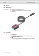
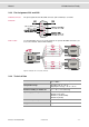
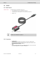
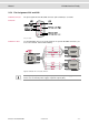
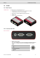
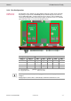
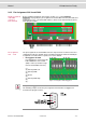
Table Of Contents
Manual VN1600 Interface Family
© Vector Informatik GmbH Version 2.0 - 18 -
2.6.5 Pin Assignment CH1/3 and CH2/4
Double assignment
of D-SUB9
connectors
CH1 and CH2
Before installing a Piggyback in the plug-in location (see section Replacing
Piggybacks on page 23), the pin assignment of the D-SUB9 connector (CH1/CH3 and
CH2/CH4) has to be selected via DIP switches, which can be found inside the device
at the plug-in locations.
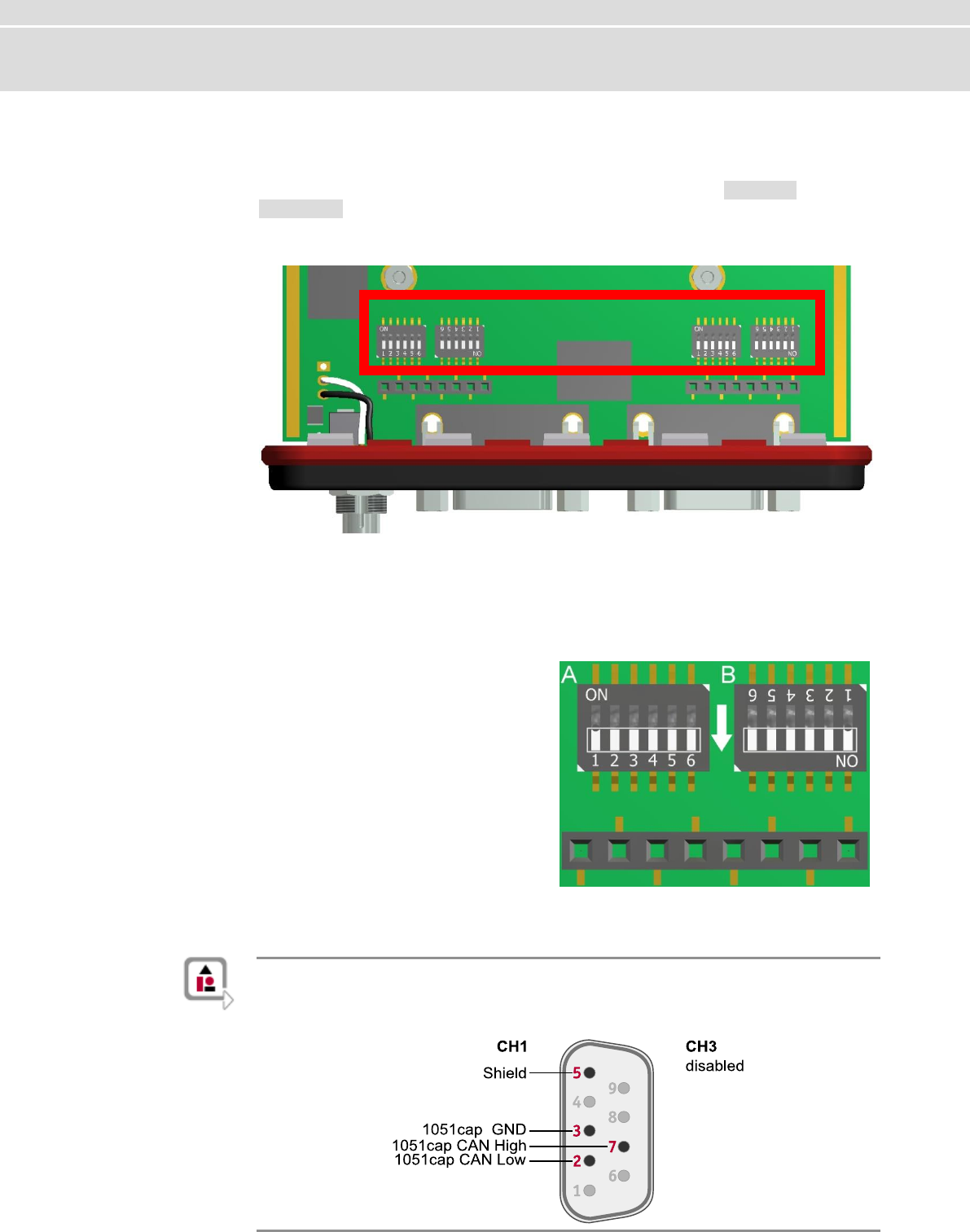
Figure 11: DIP switches (left: CH1/3, right: CH2/4).
Pin assignment
CH1 … CH4
The pin assignments of the D-SUB9 connectors depend on the used bus transceiver
configuration inside the VN1630. A list of available Piggybacks and their D-SUB9 pin
assignments is included in the separate accessories manual.
> No Piggyback inserted
If no Piggyback is inserted, only the
built-in CAN transceiver at CH1
(CH2) is active (no double assign-
ment of the D-SUB9 connector):
(1) -
(2) 1051cap CAN Low
(3) 1051cap GND
(4) -
(5) Shield
(6) -
(7) 1051cap CAN High
(8) -
(9) -
A: all ‚OFF’ B: all ‚ON’
Figure 12: Configuration without Piggyback.
Example: No Piggyback
The following example shows the pin assignment of CH1/CH3 if no Piggyback is
inserted in the plug-in location 1.
Piggy 1 (CH1/3)
Piggy 2 (CH2/4)