
Automobile Parts User Manual

INSTALLATION DIRECTIVEMAY 2006
23
V08 ENT M75
-
M11
-
M12
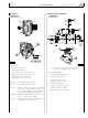
Supplementary services battery
To assure that the engine can be started with a sufficient
quantity of energy, it is advisable to provide for the instal-
lation of a supplementary battery, dedicated to supplying
power to the on-board electrical services. The power line to
recharge it may be constructed according to the indications
provided in Chapter 20.
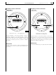
If one engine is installed
The battery used for services may be recharged interposing
on the power supply line a relay actuated by the recharge
signal of the alternator’s electronic regulator (L).
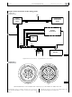
If two engines are installed
The presence of two generators allows keeping the recharg-
ing functions separated: the generator (G1) recharges the
battery (AC1) dedicated to starting both engines and pow-
ering both electrical/electronic control circuits, whilst the
generator (G2) recharges the battery (AC2) used to power
the services.
In two-engine applications, it is essential to connect the
engine grounds to a common potential; the solution pro-
posed in Chapter 20 fully complies with this need, assuring
the full functionality and independence of the two circuits.
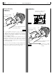
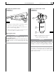
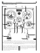
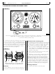
Relay Box
1. Control selector from bridge or engine room - 2. Power
supply switch of the engine electric circuits - 3. Start button
from engine room - 4. Reset button of the “maintenance
alarm” 5. Button for managing acceleration and deceleration
- 6. Connector for diagnostic instrument -
7. Blink code emission LED (EDC) - 8. Signalling LED of
maintenance interval expiration - 9. Signalling LED for fault
engine operating parameters (WARNING).
This shall be installed and anchored in such a way as to
dampen the vibrations and stresses occurring when under-
way, and they shall be accessible during servicing operations
and when underway. The electrical commands positioned
on the panel allow controlling engine starting and stopping
directly from the engine room, while excluding any possibil-
ity that anyone may involuntarily start the engine from the
bridge, during servicing operations.
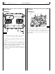
On the relay box is located the multipolar connector (6),
protected by a screw-on lid, for connection with the com-
puterized diagnostic tools prescribed by IVECO MOTORS.
Inside the box, anchored to a printed circuit board, are pres-
ent the power management relays of some components and
the elements that protect the electrical lines against short
circuits or excessive current absorption. These components
perform a similar function to that of fuses, almost totally
avoiding the need to restore the electrical continuity of cir-
cuits subjected to an anomaly condition. These components
are able to limit and eliminate short circuit currents without
melting, restoring their own and the circuit’s electrical conti-
nuity, once the cause of the anomaly is removed.
Figure 18
"2)$'%
2//-
)'.)4)/. 34!24 20-
20-
%.').%
#(%#+
3
05_007_V
2 54 6
9 8 7
1