
Operating instructions


Faults and Alarms Vector Control Chassis Type Frequency Converter
476 869 4070 76 J AB-74 Siemens AG
11-2 Operating Instructions SIMOVERT MASTERDRIVES
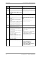
Fault
number
Fault Counter-measure
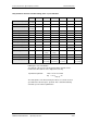
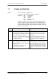
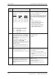
F006 DC link overvoltage
Shutdown has occurred due to excessive DC
link voltage.
Line voltage I DC voltage I Shutdown
I range I threshold
200 V - 230 V I 270 V – 310 V I appr. 410 V
380 V - 480 V I 510 V – 650 V I appr. 820 V
500 V - 600 V I 675 V – 810 V I appr. 1020 V
660 V - 690 V I 890 V – 930 V I appr. 1220 V
Check the supply voltage or input DC voltage.
Converter is operating in regenerative mode
without rectifier possibility.
If the converter supply voltage is at the upper
tolerance limit and it is operating at full load,
F006 can also be caused by a line phase
failure.
Possibly:
• Increase P464 Decel Time,
• Activate P515 DC Bus Volts Reg
(check P071 beforehand)
• Reduce P526 Fly Search Speed.
• Reduce P259 Max Regen Power
(only for P100 = 3, 4 or 5)
For parallel-connected converters (BF L)
r949 = 1: Overvoltage in the DC link
of the master
r949 = 2: Overvoltage in the DC link
of the slave.
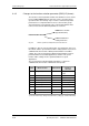
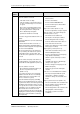
F008 DC link undervoltage
The lower limit value of 76 % of the DC link
voltage (P071 Line Volts), or of 61 % when
kinetic buffering has been enabled, has been
fallen short of.
Undervoltage in the DC link in ’normal’
operation (i.e. no SIMULATION).
Undervoltage in the DC link with active kinetic
buffering and speed less than 10 % of the
rated motor speed.
It was a ’brief power failure’ which was not
detected until system recovery (auto restart
flag).
Check:
• Input DC voltage
• DC link
F011 Overcurrent
Overcurrent shutdown has occurred.
The shutdown threshold has been exceeded.
Check
• the converter output for short-circuit or
ground fault
• the load for an overload condition
• whether motor and converter are correctly
matched
• whether the dynamic requirements are too
high.
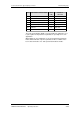
F012 I too low
During excitation of the induction motor, the
current did not rise above 12.5 % of the
setpoint magnetizing current for no-load
operation.
Only for closed loop n/f/T control
(P100 = 3, 4 or 5)
If no motor is connected, go into the
simulation mode P372.
Check current detection, check power
section.