
Operating instructions


Faults and Alarms Vector Control Chassis Type Frequency Converter
476 869 4070 76 J AB-74 Siemens AG
11-4 Operating Instructions SIMOVERT MASTERDRIVES
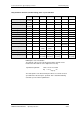
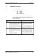
Fault
number
Fault Counter-measure
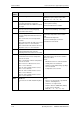
F017 SAFE OFF in operation
Check whether the switch for SAFE OFF
(X009/5-6) is open (only for devices with
Order No....-11, ...-21,...-31,...-61).
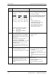
F018 F set fly
The found set-frequency could not be
implemented because the additional setpoint
is too high.
Check additional setpoint.
Power up after coasting.
Release both directions of rotation.
F019 Motor not found
Motor has not been found (during flying
restart without tachometer).
Power up after coasting.
Possibly increase P525 Fly Search Amps.
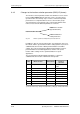
F020 Motor temperature
The motor temperature limit value has been
exceeded.
r949 = 1 Limit value of motor temperature
exceeded
r949 = 2 Short-circuit in the cable to the motor
temperature sensor or sensor defective
r949 = 3 wire break in the cable to the motor
temperature sensor or sensor defective
Check the motor (load, ventilation, etc.). The
actual motor temperature can be read in
r009.
Check P381 Mot Tmp Fault
Check the KTY84 input at connector
X103:29,30 for short-circuit.
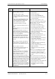
F021 Motor I2t
Parameterizable limit value of the I2t
monitoring for the motor has been exceeded.
Check: P383 Mot Tmp T1
F023 Inverter temperature
The limit value of the inverter temperature
has been exceeded.
r949 = 1: Limit value of inverter temperature
has been exceeded.
r949 = 2: Sensor 1: Wire break of sensor
cable or sensor defective
r949 = 18: Sensor 2: Wire break of sensor
cable or sensor defective
r949 = 34: Sensor 3: Wire break of sensor
cable or sensor defective
r949 = 50: Sensor 4: Wire break of sensor
cable or sensor defective
Measure the air intake and ambient
temperature. Please observe the reduction
curves at ϑ >40 ºC.
Check:
• Whether the fan -E1 is connected and is
rotating in the correct direction.
• That the air entry and discharge openings
are not restricted.
• Temperature sensor at -X30
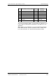
F025 UCE Ph. L1
There has been an UCE shutdown in phase
L1.
Check:
• Phase L1 for short-circuit or ground fault
(-X2:U2 – including motor).
• That CU is correctly inserted.
• That the switch for ‘SAFE OFF’ (X9/5-6)
is open (only for units with
Order No. ...-11, ...-21,...-31,...-61).