
Operating instructions


Vector Control Chassis Type Frequency Converter Faults and Alarms
SIEMENS AG 476 869 4070 76 J AB-74
SIMOVERT MASTERDRIVES Operating Instructions 11-19
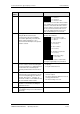
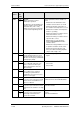
Alarm
number
Param.
No.
Bit No.
Cause Counter-measure
A035 r955
2
Wire break
The clockwise and/or the counter-
clockwise rotating field is not
enabled, or a wire breakage is
present in the terminal wiring (both
control word bits are zero)
Check whether cable(s) to the
corresponding digital input(s),
P572 Src REV Speed/ P571 Src FWD
Speed is (are) interrupted or released.
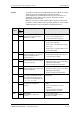
A036 Brake checkback "Brake still
closed“
Check the brake checkback (see FD 470)
A037 Brake checkback "Brake still
open"
Check brake checkback (see FP 470)
A041
r955
8
Vdmax controller inhibit
The line voltage is too high or the
drive line voltage (P071) is
incorrectly parameterized. The
Vdmax controller is disabled despite
parameter access (P515), as
otherwise the motor would
accelerate immediately in operation
to the maximum frequency.
Check:
• Line voltage
• P071 Line Volts
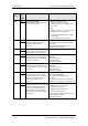
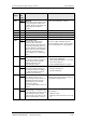
A042 r955
9
Motor stall/lock
Motor is stalled or locked.
The alarm cannot be influenced by
P805 “ PullOut/BlckTime”, but by
P794 “Deviation Time”.
Check:
• Whether the drive is locked.
• Whether the encoder cable is interrupted
during speed control and whether the
shield is connected.
• Whether the drive has stalled.
• For synchronous motors (P095=12):
excitation current injection
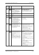
A043 r955
10
n-act jump
The permissible change value of the
speed encoder signal (P215) has
been exceeded.
Additionally for synchronous motors
(P095=12):
The motor rotates with more than 2
% of the rated speed at the time of
inverter release. The inverter status
"Ready for operation" is not exited.
Check the tachometer cables for
interruptions.
Check the earthing of the tachometer shield.
• The shield must be connected both on
the motor and on the converter side.
• The encoder cable must not be
interrupted.
• The encoder cable must not be laid with
the power cables.
• Only the recommended encoders should
be used.
• If there is a signal fault, use the DTI
board if necessary.
If necessary, change P215
• Additionally for synchronous motors
(P095=12):
Do not grant inverter release until the
motor is at standstill.