
Operating instructions


Maintenance Vector Control Chassis Type Frequency Converter
476 869 4070 76 J AB-74 Siemens AG
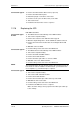
12-6 Operating Instructions SIMOVERT MASTERDRIVES
12.7 Replacing the SML and the SMU
SML: Snubber Module Lower
SMU: Snubber Module Upper
♦
Remove the capacitor battery.
♦
Undo the fixing screws (4 x M8, 8 - 10 Nm or 4 x M6, 2.5 - 5 Nm, 1 x
M4, max 1.8 Nm).
♦
Remove the modules.
Install the new modules in the reverse sequence.
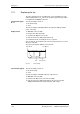
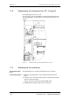
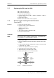
12.8 Removing and installing the module busbars
(from type G)
♦
Remove the capacitor battery.
♦
Undo the screws of the module busbars.
M8 power connections
M6 fastening on spacers
M4 circuit.
♦
Take out the insulation of the SMU / SML.
♦
Lift out the module busbars.
The spacing between the plus busbar and the minus busbar must be at
least 4 mm. In order to install the module busbars, you must therefore
use a template, e.g. a 4 mm thick piece of plastic.
♦
Place the module busbars and SMU/SML insulation on spacer bolts
and fix in place (M6).
♦
Place the template instead of the DC link bus module in the module
busbars.
♦
Locate the SMU and SML and tighten the modular connections (M8,
8 - 10 Nm, M6, 2.5 - 5 Nm).
♦
Screw the nuts tight on the spacer bolts (6 Nm).
♦
Connect the circuit resistors (M4, 1.8 Nm).
♦
Tighten the power connections (M8, 13 Nm).
♦
Remove the template from the module busbars.
Module screw
connection
+
Module
screw con-
nection
−
Template 4 mm
4
Fig. 12-4 Installing the module busbars
Removal
Installation
NOTE