
Operating instructions


Maintenance Vector Control Chassis Type Frequency Converter
476 869 4070 76 J AB-74 Siemens AG
12-8 Operating Instructions SIMOVERT MASTERDRIVES
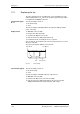
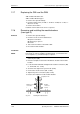
12.12 Replacing the rectifier module
♦
Remove the PCC and the PCU.
♦
Dismantle the input bus module and the rectifier bus module.
♦
Undo the screws of the faulty module and remove it.
♦
Remove the PCC together with the support plate
♦
Remove the PCU, PSU and the electronics box.
♦
Dismantle the input bus module and the rectifier bus module.
♦
Install the new PCU in the reverse sequence.
♦
Coat the contact surfaces of the heat sink thinly and evenly with a
thermo-lubricant.
♦
Tighten the fixing screws of the rectifier module with 4 Nm.
♦
Re-install the remaining components in the reverse sequence.
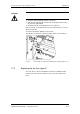
12.13 Replacing the IVI
IVI: Inverter-Value Interface (interface board for the power section)
The IVI board is screwed on at the rear of the electronics box.
♦
Withdraw the connections X205, X206, X208, X31 and X33 from the
IVI board.
♦
Remove the capacitor battery (types E and F).
♦
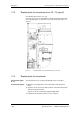
Disconnect the fiber-optic cables (type G with rated input voltage
3 ph. AC 660 - 690 V or DC 890 - 930 V).
♦
Remove the PSU together with its insulation (type G)
♦
Take all the units out of the electronics box and place them on a
suitable surface which is not statically charged.
♦
Undo the two fixing screws of the electronics box.
♦
Push the electronics box out of its interlock and remove it towards
the front.
♦
Pull out the ABO adaption board.
♦
Unscrew the IVI board and take it out.
♦
Install the new IVI in reverse sequence.
Removal
Construction types
E and F
Construction type G
Installation
Construction types
E to G