
Operating instructions


Vector Control Chassis Type Frequency Converter Maintenance
SIEMENS AG 476 869 4070 76 J AB-74
SIMOVERT MASTERDRIVES Operating Instructions 12-11
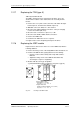
12.17 Replacing the TDB (type K)
TDB: Thyristor Drive Board
The TDB is arranged in front of the thyristor modules. These are
situated in the rectifier section between the fan assembly and the
inverter.
♦
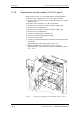
Remove the cover (undo screws, then first of all detach the right-
hand snap hook, and then the left-hand snap hook)
♦
Withdraw connectors X246, X11, X12 and X13.
♦
Disconnect the PUD and NUD connections of the pre-charging
resistors R1 and R2 (M4, Torx).
♦
Disconnect the connections to phases U, V, W .
♦
Disconnect the NUD1, NUD2, NUD3 connections.
♦
Remove the TDB board.
♦
Install the new TDB in the reverse sequence.
See figure under section "Replacing the thyristor modules"
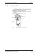
12.18 Replacing the IGBT module
Replacement is carried out as in the case of the IGD board, with the
following additions:
♦
Remove the fixing screws of the faulty IGBT module and take it out.
♦
Install a new IGBT module, paying attention to the following:
•
Coat the contact surfaces thinly and evenly with a thermo-
lubricant.
•
Tighten the fixing screws of the IGBT module with 5 Nm,
observing the sequence of tightening.
♦
Modules with the same type designation
e.g. FZxxxxRYYKF4 must be installed in every phase (type K).
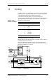
5
1
36
2
4
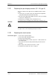
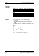
Screw on IGBT module:
1. Hand-tighten (~ 0.5 Nm)
Sequence 1 - 2 - 3 - 4 - 5 - 6
2. Tighten with 5 Nm
(Order No. 6SE7031-8EF60: 2.5 - 3.5 Nm)
Sequence 1 - 2 - 3 - 4 - 5 - 6
13
42
CE
Fig. 12-5 Screwing on the IGBT module