
Operating instructions


Installation Vector Control Chassis Type Frequency Converter
476 869 4070 76 J AB-74 Siemens AG
5-2 Operating Instructions SIMOVERT MASTERDRIVES
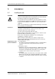
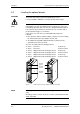
5.1.1 Installing units of types E, F, G
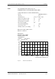
Mounting surface
350 mm
Cooling air
Type
Clearances
[mm]
E,F
400
G
320
Fig. 5-1 Minimum clearances for cooling air requirement (types E, F, G)
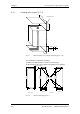
The following are required for mounting:
♦
Dimension drawing for the relevant construction type
♦
M8 or M10 screws, refer to dimension drawing for the quantity
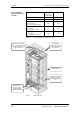
Side view
Type E
350 mm
1050 mm
Mounting surface
Cutouts
for M8 screw
1025 mm
10 mm
180 mm
270 mm
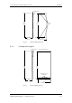
Type F
1025 mm
10 mm
270 mm
360 mm
Front view
Fig. 5-2 Dimension drawing for types E, F