
Operating instructions
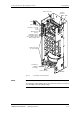

Connecting-up Vector Control Chassis Type Frequency Converter
476 869 4070 76 J AB-74 Siemens AG
7-6 Operating Instructions SIMOVERT MASTERDRIVES
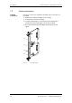
The protective conductor has to be connected both on the line side and
on the motor side. It has to be dimensioned according to the power
connections.
The "braking unit" and "dv/dt filter" options can be connected up to the
DC link terminals C/L+ and D/L-. These terminals are not suitable for
connecting up other inverter units (e.g. DC units).
This connection is not suitable for connecting up a rectifier or
rectifier/feedback unit.
With the M65 option, it is possible to move the DC link terminals to the
bottom of the unit.
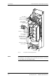
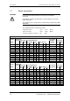
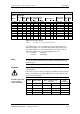
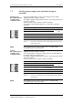
Due to the 230 V fan a transformer is integrated into the converters.
The terminals on the primary side must be connected corresponding to
the rated input voltage.
Due to the 230 V fan a transformer is integrated into the converters.
The terminals on the primary side have to be reconnected according to
the rated input voltage, if necessary.
If this is not done, the fuses F3, F4 or F101, F102 may blow.
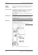
Fig. 7-3 Fan transformer (-T10), fan transformer fuses (-F3, -F4)
Protective
conductor
connection
DC link connection
NOTE type E to G
NOTE Type K