
Operating instructions

Vector Control Chassis Type Frequency Converter Connecting-up
SIEMENS AG 476 869 4070 76 J AB-74
SIMOVERT MASTERDRIVES Operating Instructions 7-9
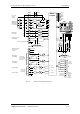
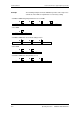
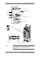
Bidirectional
digital inputs-
and outputs
I
out
≤
20 mA
X101
5V
24V
In
Out
Out
In
Out/In
In
Out
In
Out
In
Out
In
Out
In
4 bidirectional digital inputs/outputs
Outputs
Reference voltage
P10 V / N10 V
I
≤
5 mA
P24V
M24
Aux. power
supply
150 mA
Analog input 1
(non-floating)
5V
24V
In
Inputs
5V
24V
2
1
3
4
5
6
7
8
9
10
11
12
Micro-
controller
P5V
RS485P
BOOT
RS232 TxD
≥
1
Digital inputs
Ri = 3,4 k
Ω
123456789
RS232 RxD
RS485N
PMU
X300
13
14
P10 AUX
N10 AUX
Slot C
Slot D
Slot E
Slot F
Slot G
Slot A
+5V
S1
Switch for USS bus connection
BOOT
n.c.
Controller
15
16
19
20
D
A
D
A
In
5V
24V
+5V
S2
Switch for USS bus connection
RS485N
RS485P
UART
Reference potential RS485
Serial interface 2
USS (RS485)
S3
12
17
18
D
A
S3
34
S4
1
2
3
-10...+10 V
0...+20 mA
21
22
D
A
S4
4
5
6
-10...+10 V
0...+20 mA
M
M
X102
In
In
A
S
I
C
30
29
28
27
26
25
24
23
Track A
Track B
Tacho M
Zero pulse
Control
Tacho P15
Mot. temp BS
Mot.temp
X103
Pulse
encoder
I≤190 mA
Motor
temperature
sensor
KTY84
or PTC
thermistor
AI 1
AI 2
Analog input 2
(non-floating)
11 bit + sign
U: R
in
= 60 kΩ
I: R
in
= 250
Ω
(Close S3)
10 bit + sign
U: I ≤ 5 mA
I: R ≤ 500 Ω
AO 1
AO 2
Analog output 1
Analog output 2
Fig. 7-5 Overview of the standard connections