
Operating instructions

Connecting-up Vector Control Chassis Type Frequency Converter
476 869 4070 76 J AB-74 Siemens AG
7-10 Operating Instructions SIMOVERT MASTERDRIVES
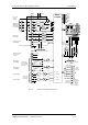
The following connections are provided on the control terminal strip:
♦
4 optionally parameterizable digital inputs and outputs
♦
3 digital inputs
♦
24 V aux. voltage supply (max. 150 mA) for the inputs and outputs
♦
1 serial interface SCom2 (USS / RS485)
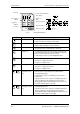
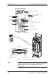
Terminal Designation Significance Range
1 P24 AUX Aux. voltage supply DC 24 V / 150 mA
2 M24 AUX Reference potential 0 V
3 DIO1 Digital input/output 1 24 V, 10 mA / 20 mA
4 DIO2 Digital input/output 2 24 V, 10 mA / 20 mA
5 DIO3 Digital input/output 3 24 V, 10 mA / 20 mA
6 DIO4 Digital input/output 4 24 V, 10 mA / 20 mA
7 DI5 Digital input 5 24 V, 10 mA
8 DI6 Digital input 6 24 V, 10 mA
9 DI7 Digital input 7 24 V, 10 mA
10 RS485 P
USS bus connection
SCom2
RS485
11 RS485 N
USS bus connection
SCom2
RS485
12 M RS485 Reference potential RS485
Connectable cross-section: 1.5 mm² (AWG 16)
Terminal 1 is at the top when installed.
Table 7-5 Control terminal strip X101
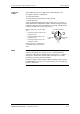
X101 – Control
terminal strip