
Operating instructions
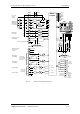
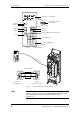

Connecting-up Vector Control Chassis Type Frequency Converter
476 869 4070 76 J AB-74 Siemens AG
7-12 Operating Instructions SIMOVERT MASTERDRIVES
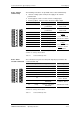
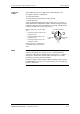
Either an OP1S or a PC can be connected up via the 9-pole Sub D
socket.
Pin Name Significance Range
1 n.c. Not connected
2 RS232 RxD Receive data via RS232 RS232
3 RS485 P Data via RS485 RS485
4 Boot Control signal for software update Digital signal, low
active
5 M5V Reference potential to P5V 0 V
6 P5V 5 V aux. voltage supply +5 V, Imax = 200 mA
7 RS232 TxD Transmit data via RS232 RS232
8 RS485 N Data via RS485 RS485
9 n.c. Not connected
Table 7-8 Serial interface X300
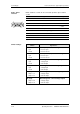
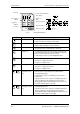
Switch Significance
S1
• open
• closed
SCom1 (X300): Bus terminating resistor
• Resistor open
• Resistor closed
S2
• open
• closed
SCom2 (X101/10,11): Bus terminating resistor
• Resistor open
• Resistor closed
S3 (1,2)
• open
• closed
AI1: Changeover current/voltage input
• Voltage input
• Current input
S3 (3,4)
• open
• closed
AI2: Changeover current/voltage input
• Voltage input
• Current input
S4 (1,2,3)
• Jumper 1, 3
• Jumper 2, 3
AO1: Changeover current/voltage output
• Voltage output
• Current output
S4 (4,5,6)
• Jumper 4, 6
• Jumper 5, 6
AO2: Changeover current/voltage output
• Voltage output
• Current output
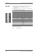
X300 - Serial
interface
15
69
Switch settings