
Operating instructions

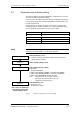

Vector Control Chassis Type Frequency Converter Parameterizing steps
SIEMENS AG 476 869 4070 76 J AB-74
SIMOVERT MASTERDRIVES Operating Instructions 9-5
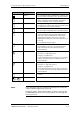
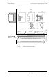
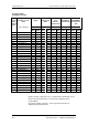
Significance of the binectors and connectors for factory setting:
Entry Description See function diagram
(in Compendium)
B0000 Fixed binector 0 -15.4-
B0001 Fixed binector 1 -15.4-
B0005 PMU ON/OFF -50.7-
B0008 PMU MOP UP -50.7-
B0009 PMU MOP DOWN -50.7-
B0010 DigIn1 -90.4-
B0012 DigIn2 -90.4-
B0014 DigIn3 -90.4-
B0016 DigIn4 -90.4-
B0018 DigIn5 -90.4-
B0020 DigIn6 -90.4-
B0022 DigIn7 -90.4-
B0100 Rdy for ON -200.5-
B0104 Operation -200.5-
B0107 No fault -200.6-
B0108 No OFF2 -200.5-
B0120 CompV OK -200.5-
B2100 SCom1 Word1 Bit0 -100.8-
...
B2115 SCom1 Word1 Bit15 -100.8-
B4100 SCI1 Sl1 DigIn -Z10.7- / -Z30.4-
...
B4115 SCI1 Sl1 DigIn -Z30.8-
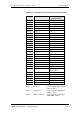
r229 n/f(set,smooth) -360.4- / -361.4- / -362.4- /
-363.4- / -364.4-
P405 Fixed setpoint 5 -290.3-
KK0020 Speed (smoothed) -350.8- / -351.8- / -352.8-
K0022 Output Amps (smoothed) -285.8- / -286.8-
K0024 Torque (smoothed) -285.8-
KK0040 Current FixSetp -290.6-
KK0058 MOP (Output) -300.8-
Bxxxx = Binector = freely assignable digital signal
(values 0 and 1)
Kxxxx = Connector = freely assignable 16-bit signal
(4000h = 100 %)
KKxxxx = Double connector = freely assignable 32-bit signal
(4000 0000h = 100 %)