
Operating instructions

Parameterizing steps Vector Control Chassis Type Frequency Converter
476 869 4070 76 J AB-74 Siemens AG
9-10 Operating Instructions SIMOVERT MASTERDRIVES
9.2.3 Parameterizing with parameter modules
(quick parameterization, P060 = 3)
Pre-defined, function-assigned parameter modules are stored in the
units. These parameter modules can be combined with each other, thus
making it possible to adjust your unit to the desired application by just a
few parameter steps. Detailed knowledge of the complete parameter
set of the unit is not required.
Parameter modules are available for the following function groups:
1. Motors (input of the rating plate data with automatic
parameterization of open-loop and closed-loop control)
2. Open-loop and closed-loop control types
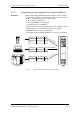
3. Setpoint and command sources
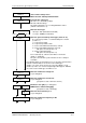
Parameterization is effected by selecting a parameter module from
each function group and then starting quick parameterization. In
accordance with your selection, the necessary unit parameters are set
to produce the desired control functionality. The parameters necessary
for fine adjustment of the control structure (all the parameters of the
respective function diagrams) are automatically adopted in the user
menu (P060 = 0).
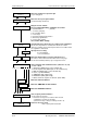
Parameterizing with parameter modules is carried out only in BICO
data set 1 and in function and motor data set 1.
Quick parameterization is effected in the "Download" converter status.
Function diagram modules (function diagrams) are shown after the flow
chart for parameter modules stored in the unit software. On the first few
pages are the :
♦
setpoint and command sources, on the following pages are the
♦
analog outputs and the display parameters and the
♦
open-loop and closed-loop control types.
It is therefore possible to put together the function diagrams to exactly
suit the selected combination of setpoint/command source and
open/closed-loop control type. This will give you an overview of the
functionality parameterized in the units and of the necessary
assignment of the terminals.
The function parameters and visualization parameters specified in the
function diagrams are automatically adopted in the user menu and can
be visualized or changed there.
The parameter numbers of the user menu are entered in P360.
Reference is made in the function diagrams to the respective function
diagram numbers (Sheet [xxx]) of the detail diagrams (in the
Compendium).
NOTE
Function diagram
modules