
Operating instructions


Vector Control Chassis Type Frequency Converter Description
SIEMENS AG 476 869 4070 76 J AB-74
SIMOVERT MASTERDRIVES Operating Instructions 2-1
2 Description
The frequency converter is a power electronics component for feeding
three-phase drives in the output range from 37 kW to 400 kW.
The unit can be operated from a three-phase system with a frequency
of 50/60 Hz and a voltage in the range of the values entered on the
rating plate (380...480 / 500...600 / 660...690 V).
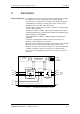
The three-phase current from the system is rectified, smoothed and fed
onto the capacitor DC link.
The inverter enables a variable output frequency between 0 Hz and a
maximum of 600 Hz to be generated from the DC current with the pulse
width modulation method (PWM).
The internal DC 24 V voltage is supplied through an integral power
supply unit.
The unit is controlled by the internal closed-loop electronics, the
functions are provided by the unit software.
Operator control is via the PMU operator control panel, the user-friendly
OP1S operator control panel, the terminal strip or via the serial
interfaces of the bus system. For this purpose, the unit is provided with
a number of interfaces and six slots for the use of optional boards.
Pulse encoders and analog tachometers can be used as encoders on
the motor.
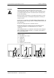
Motor
connec-
tion
U2/T1
V2/T2
W2/T3
PE2
Control electronics
Serial
interface
Terminal strip
Optional
boards
DC link
U1/L1
V1/L2
W1/L3
C / L+
D / L -
PE1
PMU
Inverter
Pre-charging
Rectifier
Fig. 2-1 Circuit principle of the frequency converter
Range of application