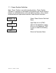
Quick Startup Guide for SIMOVERT MASTERDRIVES 6SE70 VC Vector Control Section 1: Parameterization of Base Drive Section 2: Parameterization of Rectifier Section 3: Simovis Trace Setup Method Section 4: When Should a Drive be re-Tuned DROM-02069
We reserve the right to modify functions, technical data, standards, drawings and parameters. We have checked the contents of this document to ensure that they coincide with the described hardware and software. However, deviations cannot be completely ruled-out, so we cannot guarantee complete conformance. However, the information in this document is regularly checked and the necessary corrections will be included in subsequent editions. We are thankful for any recommendations or suggestions.
NOTE: These instructions do not purport to cover all details or variations in equipment, nor to provide for every possible contingency to be met in connection with installation, operation or maintenance. Should further information be desired or should particular problems arise which are not covered sufficiently for the purchaser’s purposes, please contact your local Siemens office.
Page 4 Version 1.
Section 1: Parameterization of Base Unit SIMOVERT MASTERDRIVES 6SE70 VC Vector Control 1.1 Power Section Defintion 1.2 Factory Reset 1.3 Basic Start-up 1.3.1 Volts/Hz without encoder feedback 1.3.2 Volts/Hz with encoder feedback 1.3.3 Vector Control without encoder feedback 1.3.4 Vector Control with encoder feedback 1.4 Drive Control Word 1.5 Communication Board Configuration Note: Refer to Operating Instruction Manual for power and control connections. Version 1.
Page 6 Version 1.
1.1 Power Section Definition Note: Power Section is pre-defined at the factory. Power Section Definition is required if a new board CUVC board is put into the drive or boards are switched between units with different ratings. Drive should be defaulted and re-parameterized after Power Section Definition. P060 = 8 P070 = ? P060 = 1 Select “Power Section Definition” Menu Input Code for unit (PWE) (Refer to Compendium section 6.
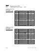
Unit List P070: P072: Parameter Value (PWE) Rated Output Current in Amps Frequency Converter AC-AC type 3 AC 200V to 230V Frequency Inverter DC-AC type DC 270V to 310V Page 8 In[A] PWE 14 21 27 32 39 48 54 64 70 13 29 41 87 Order Number 6SE7021-1CA60 6SE7021-3CA60 6SE7021-8CB60 6SE7022-3CB60 6SE7023-2CB60 6SE7024-4CC60 6SE7025-4CD60 6SE7027-0CD60 6SE7028-1CD60 6SE7031-0CE60 6SE7031-3CE60 6SE7031-6CE60 6SE7032-0CE60 In[A]*1 10.6 13.3 17.7 22.9 32.2 44.2 54.0 69.0 81.0 100.0 131.0 162.0 202.
Frequency Converter AC-AC type 3 AC PWE 380V to 460V Air Cooled 3 9 11 18 25 35 42 46 52 56 66 74 82 90 98 102 108 112 116 147 151 164 * 1 PWE Water Cooled 233 237 168 Order Number In[A]*1 6SE7016-1EA61 6SE7018-0EA61 6SE7021-0EA61 6SE7021-3EB61 6SE7021-8EB61 6SE7022-6EC61 6SE7023-4EC61 6SE7023-8ED61 6SE7024-7ED61 6SE7026-0ED61 6SE7027-2ED61 6SE7031-0EE60 6SE7031-2EF60 6SE7031-5EF60 6SE7031-8EF60 6SE7032-1EG60 6SE7032-6EG60 6SE7033-2EG60 6SE7033-7EG60 6SE7035-1EK60 6SE7036-0EK60 6SE7037-0EK60 6.1 8.
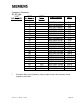
Frequency Inverter DC-AC type DC PWE 510V to 650V Air Cooled 4 10 12 19 26 36 43 47 53 57 67 75 83 91 99 103 109 113 117 120 123 126 127 134 135 140 150 153 154 163 181 185 194 Page 10 PWE Water Cooled 206 209 212 213 221 226 236 239 199 167 247 250 244 Order Number In[A]*1 6SE7016-1TA61 6SE7018-0TA61 6SE7021-0TA61 6SE7021-3TB61 6SE7021-8TB61 6SE7022-6TC61 6SE7023-4TC61 6SE7023-8TD61 6SE7024-7TD61 6SE7026-0TD61 6SE7027-2TD61 6SE7031-0TE60 6SE7031-2TF60 6SE7031-5TF60 6SE7031-8TF60 6SE7032-1TG60 6SE7032
Frequency Converter AC-AC type 3 AC PWE 500V to 575V Air Cooled 1 5 7 16 23 30 37 44 50 60 62 68 78 84 94 100 104 136 141 143 * 1 PWE Water Cooled 222 227 229 Order Number In[A]*1 6SE7014-5FB61 6SE7016-2FB61 6SE7017-8FB61 6SE7021-1FB61 6SE7021-5FB61 6SE7022-2FC61 6SE7023-0FD61 6SE7023-4FD61 6SE7024-7FD61 6SE7026-1FE60 6SE7026-6FE60 6SE7028-0FF60 6SE7031-1FF60 6SE7031-3FG60 6SE7031-6FG60 6SE7032-0FG60 6SE7032-3FG60 6SE7033-0FK60 6SE7033-5FK60 6SE7034-5FK60 4.5 6.2 7.8 11.0 15.1 22.0 29.0 34.0 46.
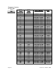
Frequency Inverter DC-AC type DC PWE 675V to 810V Air Cooled Page 12 PWE Water Cooled 2 6 8 17 24 31 38 45 51 61 63 69 79 85 95 101 105 110 114 118 121 124 128 130 132 138 144 200 202 204 207 210 214 216 218 224 230 148 234 155 157 159 195 197 Order Number In[A]*1 6SE7014-5UB61 6SE7016-2UB61 6SE7017-8UB61 6SE7021-1UB61 6SE7021-5UB61 6SE7022-2UC61 6SE7023-0UD61 6SE7023-4UD61 6SE7024-7UD61 6SE7026-1UE60 6SE7026-6UE60 6SE7028-0UF60 6SE7031-1UF60 6SE7031-3UG60 6SE7031-6UG60 6SE7032-0UG60 6SE7032-3UG6
Frequency Inverter DC-AC type DC PWE 675V to 810V Air Cooled 161 165 169 173 177 179 182 186 188 190 192 Frequency Converter AC-AC type 3 AC PWE 660V to 690V Air Cooled 58 72 76 80 88 96 106 137 142 146 Frequency Inverter DC-AC type PWE DC 890V to 930V Air Cooled 59 73 Version 1.
DC 890V to 930V Page 14 PWE Air Cooled PWE Water Cooled 77 81 89 97 107 111 115 119 122 125 129 131 133 139 145 201 203 205 208 211 215 217 219 225 231 149 235 152 156 158 160 162 166 170 174 178 180 183 187 189 191 193 238 196 198 246 249 252 254 241 243 Order Number In[A]*1 6SE7031-0WG60 6SE7031-2WF60 6SE7031-5WF60 6SE7031-7WG60 6SE7032-1WG60 6SE7033-0WJ60 6SE7033-5WJ60 6SE7034-5WJ60 6SE7035-7WK60 6SE7036-5WK60 6SE7038-6WK60 6SE7041-0WM60 6SE7041-1WM60 6SE7041-2WM60 6SE7041-4WM60 6SE70414WQ60
1.2 Factory Reset P053 = 6 P060 = 2 6: Parameter Changes permitted via PMU and Serial Interface (OP1 and PC) 2: Menu Select = Fixed Settings P366 = 0 Select Factory Setting 0: Standard P970 = 0 Start Parameter Reset 0: Parameter Reset 1: No Parameter Change Version 1.
Page 16 Version 1.
1.3 Basic Start-up without Motor Connected to Load 1.3.
P106 = NEMA Motor Nameplated efficiency (if unknown set =0.8) P106 = ? P107 = Rated Motor Frequency P107 = 60 P108 = Nameplated Rotor RPM P108 = xxxx P115 = 1 “Automatic Parameterization” P115 = 1 P340 = 3 P340 = Carrier Frequency Low # = Cooler Motor and Drive High # = Lower Motor Noise P383 = Motor Thermal Time Constant.
P453 = Maximum Reverse Speed in Percentage (usually -100%) P453 = -100 P060 = Return to Parameter Menu P060 = 1 P128 = xxxx P128 = Maximum Motor Current Options: P128 = P102 P128=1.1*P102 P128=1.5*P102 P462 = Acceleration Time in seconds P462 = xxxx P464 = Deceleration Time in seconds P464 = xxxx P443i2= 11 P443i2(Index2) = 11 Configures drive for analog input (0-10Vdc) to be active at terminals X101 pin#15 and pin#16 If 4-20mA is required closed CUVC board mounted jumper S3, position 1 and 2.
Connect External Wiring as connection diagram. Customer Connection Points Internal Connections Step 1: Dry set of contacts between terminals X101, pin#1 and pin#5 for Local/Remote Mode Selection. Jumper if not required. Step 2: Dry set of contacts between terminals X101, pin#1 and pin#8 for Coast to Stop Selection. Jumper if not required. Step 3: Dry set of contacts between terminals X101, pin#1 and pin#9 for Source of Main Start/Stop Selection.
Speed value is determined by P402. A selection of P402=100% will be a full speed reference setpoint. Step 6: Fault Status is provided by a 24 Vdc signal at terminals X101 pin#3 with respect to pin#2. Leave open if not required. Step 7: Drive Operating Status is provided by a 24 Vdc signal at terminals X101 pin#4 with respect to pin#2. Step 8: Connect external speed reference 0-10Volt or 4-20 mA (CUVC board mounted jumper S3 pin 2 and 2 must be closed for mA input).
1.3.2 Volts/Hz with Encoder Note: Complete section 1.3.1 before operating the motor with encoder feedback. P060 = 5 P060=5 Select “Drive Settings” P100 = 0 P100=0 Selects Volts/Hz with Encoder Feedback P130 = ? P130 = Select Type of Encoder 11: Pulse Encoder 15: Pulse Encoder with Zero Pulse P151 = ? P151 = Pulse Per Revolution (PPR) P060 = 1 P060 = Return to Parameter Menu Page 22 Version 1.
Additional Connection for +15 Vdc Encoder. Step 10: Set Speed Reference to 20%. Step 11: Provide Start command. Note that if Signal A and Signal B are reversed, the motor will accelerate rapidly. Step 12: Connect the motor to the load, unless the plan is to change to Vector Control. Standard Commissioning for a Volts/Hz controlled motor with feedback is complete, after adjusting only 24 parameters. Version 1.
1.3.3 Vector Control without Encoder Feedback Note: Complete section 1.3.1 (Volts/Hz control without encoder feedback). P060 = 5 P060=5 Select “Drive Settings” P100 = 3 P100=3 Selects Vector Control without Encoder Feedback P060 = 1 P060 = Return to Parameter Menu If you plan to use an encoder, go to section1.3.4, otherwise continue. P115 = 4 P115 = 4 No-Load Measurement Uncoupled motor will ROTATE.
P115=5 P115=5 Controller Optimization Alarm message “A080” will appear, and a start command must be issued within 20 seconds to perform the test, otherwise P115 will unset. This test is best performed on a coupled motor under actual conditions; however, if the load is cyclic (0-100% load variation), manual tuning may be preferred.
1.3.4 Vector Control with Encoder Feedback Note: Complete section 1.3.1 (Volts/Hz control without encoder feedback), and section 1.3.3 (Vector control without encoder feedback) Step 10: Operate the uncoupled motor if sections 1.3.1 and 1.3.3 are complete and verify operation of the motor without faults.
This test will adjust the following parameters P103, P120 Wait for display to change back to o009. Wait P115=5 P115=5 Controller Optimization Alarm message “A080” will appear, and a start command must be issued within 20 seconds to perform the test, otherwise P115 will unset. This test is best performed on a coupled motor under actual conditions; however, if the load is cyclic (0-100% load variation), manual tuning may be preferred.
Page 28 Version 1.
1.4 Drive Control Word Function Diagrams will be referred to in brackets with their number. Please refer to function diagrams in the compendium. Example [Diagram Number] Assign Digital Inputs Assign Off2(Coast Stop) Assign Off3(Quick Stop) Assign ON/OFF1 Digital Inputs/Outputs: Binector Assignments for Control may be made from Digital Inputs P555, P556 & P557 can be used to assign Coast to Stop P558, P559 & P560 can be used to assign Quick Stop P554 MUST be assigned to activate drive.
Page 30 Version 1.
1.5 Communication Board Configuration Select “Board Configuration” Menu P060 = 4 CBx Inserted? YES NO Parameterize CBx Boards See Function Diagrams P711 = ? to P721.1…5 = ? Simolink Address 0: Dispatcher (Master) >0: Transceiver (Slave) SLB Inserted? YES SLB Telegram Failure Time NO P740 = ? P741 = ? P742 = ? P740 =1 P740 = 0 P743 = 0 P745 = ? P746 = ? P749.1…8 = ? CBP Inserted? NO Version 1.0 March 1, 2000 P743=0, Automatic number of node evaluation.
Page 32 Version 1.
Section 2: Parameterization of a Rectifer Unit SIMOVERT MASTERDRIVES 6SE70 VC Vector Control 2.0 Power Section Defintion 2.1 Factory Reset Basic Start-up 2.2 Rectifier or Regen without auto-transformer 2.3 Regen with auto-transformer Version 1.
Page 34 Version 1.
2.0 Power Section Definition Note: Power Section is pre-defined at the factory. Power Section Definition is required if a new board CUR board is put into the drive or boards are switched between units with different ratings. CUR cards will exist Regen Rectifiers and Large Common Rectifiers. The smaller Common Rectifier will not have parameters. Drive should be defaulted and re-parameterized after Power Section Definition.
Unit List P070: P075: Parameter Value (PWE) Rated DC Output Current in Amps Large Common Rectifier AC-DC type 3 AC 380V to 460V PWE 103 105 109 118 3 AC 500V to 575V 3 AC 660V to 690V Page 36 In[A] Order Number 6SE7038-2EH85-0AA0 6SE7041-0EH85-0AA0 6SE7041-3EK85-0AA0 6SE7041-8EK85-0AA0 In[A 821.0 1023.0 1333.0 1780.0 101 104 107 111 120 6SE7037-7FH85-0AA0 6SE7041-0FH85-0AA0 6SE7041-3FK85-0AA0 6SE7041-5FK85-0AA0 6SE7041-8FK85-0AA0 774.0 1023.0 1285.0 1464.0 1880.
Regenerative Rectifier AC-DC type 3 AC PWE 380V to 460V Air Cool 14 20 31 39 42 48 51 54 57 63 66 73 79 3 AC 500V to 575V Version 1.0 PWE Water Cool Order Number In[A] 6SE7022-1EC85-1AA0 6SE7024-1EC85-1AA0 6SE7028-6EC85-1AA0 6SE7031-7EE85-1AA0 6SE7032-2EE85-1AA0 6SE7033-1EE85-1AA0 6SE7033-8EE85-1AA0 6SE7034-6EE85-1AA0 6SE7036-1EE85-1AA0 6SE7038-2EH85-1AA0 6SE7041-0EH85-1AA0 6SE7041-3EK85-1AA0 6SE7041-8EK85-1AA0 21.0 41.0 86.0 173.0 222.0 310.0 375.0 463.0 605.0 821.0 1023.0 1333.0 1780.
Regenerative Rectifier AC-DC type 3 AC PWE 660V to 690V Air Cool 36 43 47 53 56 62 68 72 75 81 Page 38 PWE Water Cool Order Number In[A] 6SE7031-4HE85-1AA0 6SE7032-2HE85-1AA0 6SE7032-7HE85-1AA0 6SE7034-2HE85-1AA0 6SE7035-3HE85-1AA0 6SE7037-7HH85-1AA0 6SE7041-0HH85-1AA0 6SE7041-3HK85-1AA0 6SE7041-5HK85-1AA0 6SE7041-8HK85-1AA0 140.0 222.0 270.0 420.0 536.0 774.0 1023.0 1285.0 1464.0 1880.0 Version 1.
2.1 Factory Reset P051 = 3 P51=3 : Export Mode P052 = 2 P52=2: Function select “Initialization” P077 = 0 P077=0 for standard default P052 = 0 P052 = 1 Version 1.
Page 40 Version 1.
2.2 Basic Start-up (Regenerative Rectifier without Autotransformer) P051 = 2 P053 = 6 P051=2 Select “Basic Mode Settings” P053 =6 Access Parameter P052 = 5 P052 = 5 Drive Settings P071 = 460 P071 = Input Rectifier Voltage Generally = 460 Volt P320 = 20 P320 = 20 Smooth Load Amps, to prevent input line sags from effecting the DC BUS regulator P773= 1.00 Deadband Converter, to prevent “toggling” between Regen and Rectifier bridges. P773 = 1.00 Version 1.
P052 = 21 P052 = 0 With DC BUS connected to the COMMON DC BUS of the system, set P52=21 and provide a start command at terminal X101, pin #9 The circuit identification test will take about 10 seconds. P052=0 Drive back to ready mode. Standard Commissioning for a Common Rectifier or a Regenerative Rectifier without Autotransformer is complete, after adjusting only 8 parameters. Page 42 Version 1.
Connect External Wiring as connection diagram. Customer Connection Points Internal Connections Step 1: Dry set of contacts between terminals X101, pin#6 and pin#13 for Local/Remote Mode Selection. Jumper if not required. Step 2: Dry set of contacts between terminals X101, pin#6 and pin#10 for Coast to Stop Selection. Jumper if not required. Step 3: Dry set of contacts between terminals X101, pin#6 and pin#9 for Source of Main Start/Stop Selection.
Page 44 Version 1.
2.3 Basic Start-up (Regenerative Rectifier with Autotransformer) P051 = 2 P053 = 6 P051=2 Select “Basic Mode Settings” P053 =6 Access Parameter P052 = 5 P052 = 5 Drive Settings P071 = 460 P071 = Input Rectifier Voltage Generally = 460 Volt P320 = 20 P320 = 20 Smooth Load Amps, to prevent input line sags from effecting the DC BUS regulator P773= 1.00 Deadband Converter, to prevent “toggling” between Regen and Rectifier bridges. P773 = 1.00 Version 1.
P571=0 Selects Autotransformer P571 = 0 P318 = 95 P052 = 21 P052 = 0 P318 = 95% Selects percentage of nominal DC BUS voltage. In cases where the input line voltage is dependable a setting of 100% is permissible. With DC BUS connected to the COMMON DC BUS of the system, set P52=21 and provide a start command at terminal X101, pin #9 The circuit identification test will take about 10 seconds. P052=0 Drive back to ready mode.
Section 3: Simovis Trace Setup Method SIMOVERT MASTERDRIVES 6SE70 VC Vector Control Version 1.
Page 48 Version 1.
3.0 Simovis Trace Load Simovis from Vector Control Documentation CD Option: To speed up your communication link set the drive P701 = 38,400 with the PMU and configure Simovis for 38,400 communication. Launch Simovis from Desktop Icon Add a Drive in Simovis Bus Configuration A C A B Select USS Bus Address, Drive and SW Version. Note: Proper Simovis Cable must be used. (RS 232) C B Version 1.
Double Click Selected Drive to start Simovis Window Verify Drive Connection Green Box should be lit up in the lower left corner A Select Trace from Diagnostics Menu Bar B B A Page 50 Version 1.
Select Record Settings in the Lower Left Corner A Select Desired Channels to Record B Set the Record Interval and Pre-trigger C Each Interval = (4.0 / P340) seconds. Pre-trigger is in Percentage (%). To Trigger With a Binector, Select: Trigger Channel = K431 Trigger Condition “=” “1 Hex” Select Trigger Channel D Function Diagram [720] K431 is the output of a Binector to Connector Converter that will be configured on the following page. B C D A Version 1.
Select “Function Block Grafics” from the Parameter Menu Bar A The block activated by Parameter U952.89 is selected with 289. Select Function Number 289 Zoom X 2 (with right Mouse click) B Set Trigger Binector in U076.01 (i.e. U076.01 = 18 Din5) Activate Block U952.89 = 4 To Configure the Trace to Trigger with a Binector follow instructions on this page. C Function Diagram [720] K431 can now be used to trigger the Trace function when Binector (i.e. DIN 5) is asserted high.
Go to the Trace Window (Diagnostics Menu – Trace) A Verify Record Settings B Start Trace C Trigger Trace Observe Status Message D A B Version 1.
Select Data Trace Scale Vertical Axis A Click Data Set to make it Active Click and Drag scale to shift it up and down. B Y▲& Y ▼ to change Scale Scale Horizontal Axis C Note: Background can be changed with right mouse click. Traces can be saved for reference. Click and drag “T” marker to shift Horizontal Scale. Move “[ ]” to change scale A B C Page 54 Version 1.
Section 4: When to Re-Tune the Drive SIMOVERT MASTERDRIVES 6SE70 VC Vector Control Version 1.
Page 56 Version 1.
4.0 Conditions that would merit re-tuning the drive Hardware additions made to the drive, such as an output reactor or a dv/dt filter. Physical changes to the process, such as the motor being changed (even if the it is an identical motor, bearing changes and coupling changes can have an influence on performance), gearbox changes, length of motor cables changed. Process changes, such as motor loading, and speed range changes to name a few.