7138 AUTINOR Installation Manual SERIE 32 MLIFT VECTOR Programmation Vectorielle Programme: B-HB32 Programme: VSC-V02 Version of 29 November 2000
WARNING This manual is deemed correct on going to press. The information contained has been scrupulously checked. However AUTINOR declines all responsibility for error or omission. Should you notice any discrepancy or unclear description, or if you have any suggestions, we would appreciate your written comments (by mail fax or Email) to: Société AUTINOR - Service Documentation Z.A. Les Marlières 59710 AVELIN [33] 03-20-62-56-00 ¬ [33] 03-20-62-56-41 autinor@autinor.
PREAMBLE Handling advice for equipment: Whatever the load, handling operations can be dangerous (collision, dropping, crushing,…). Whenever possible use mechanical handling rather than manual handling. When manual handling can not be avoided, respect the rules. At European level, these rules are set out in the Directive 90/269/CEE, Council Directive dated 19 May 1990 "concerning minimal heath and safety instructions for manual load handling with risks, to the worker, notably in the lower spinal area".
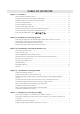
TABLE OF CONTENTS Chapter I - Generalities ......................................................................................................................... 11 How to install the controller cabinet ........................................................................................... Controller position and electromagnetic compatibility ............................................................... Minimum connections necessary for initial movement .............................................
TABLE OF CONTENTS Chapter V - Installation & connecting on Landing (continued) Landing calls for single automatic operation, 2 to 16 levels ....................................................... Landing calls for collective operation, 1 button, 2 to 8 levels ..................................................... Landing calls for collective operation, 1 button, 2 to 16 levels ................................................... Landing calls for full collective operation, 2 to 16 levels .....................
TABLE OF CONTENTS Chapter VI - Installation & connecting in Car (continued) Model with light less than to 1, 2 W (total 2,4 W max), car direction arrows ............................. Model with light superior to 1, 2 w (total 2,4 w max), car direction arrows ............................... Inspection mode ........................................................................................................................... Inspection limit switch .........................................................
CHAPTER I GENERALITIES
Série 32 Mlift Vector - Prog.Vectorielle Installation manual Chapter I - page 12 HOW TO INSTALL THE CONTROLLER CABINET For model 2 to 6 FURTHER BASE For resistive resistors (RR) SUPPORT BAR fixing with 2 screws Ø 6,3 x 38 and wall plug Ø 8 (supplied).
Série 32 Mlift Vector - Prog.Vectorielle Installation manual Chapter I - page 13 CONTROLLER POSITION AND ELECTROMAGNETIC COMPATIBILITY (1/4) When the machine room supports or is near a radio or television reception aerial, do not put the controller cabinet in the aerial receiving zone (figure 1).
Série 32 Mlift Vector - Prog.Vectorielle Installation manual Chapter I - page 14 ELECTROMAGNETIC COMPATIBILITY PRECAUTIONS (2/4) At not time should the screening cable replace the yellow-green earthing cable. ADVICE: In order to ensure the electromagnetic compatibility, it may be necessary to use to connect to the motor, a metal stuffing box with a screening contact allowing an efficient electrical link between the flat screening cable and the metal housing (see figure below).
Série 32 Mlift Vector - Prog.Vectorielle Installation manual Chapter I - page 15 ELECTROMAGNETIC COMPATIBILITY PRECAUTIONS (3/4) CONCERNING THE SET OF WIRING IN THE LANDING COLUMN SEPARATION.
Série 32 Mlift Vector - Prog.Vectorielle Installation manual Chapter I - page 16 USE OF DIFFERENTIAL CIRCUIT BREAKERS WITH AUTINOR FREQUENCY DRIVES (4/4) First of all as a reminder : • The low voltage directive explicitly states that electrical lift installations are excluded from its field of application and so the standards relating to electrical installations only applies as far as the input terminals of the main lift installation switch (cf EN 81 § 13.1.1.
Série 32 Mlift Vector - Prog.
Série 32 Mlift Vector - Prog.Vectorielle Installation manual Chapter I - page 18 MINIMUM CONNECTIONS NECESSARY FOR INITIAL MOVEMENT (1/4) GD 1 INCREMENTAL ENCODER HENGSTLER +24 RED 0V BLACK CAI WHITE CBI GREEN 3 GM To be installed in the safety lane Θ 0V STH GD GM 0V 0V 2 INS Cut the wires which are not used. Screening cable do not connect. Wires CAI and CBI should be crossed in dependance of your configuration.
Série 32 Mlift Vector - Prog.Vectorielle Installation manual Chapter I - page 19 MINIMUM CONNECTIONS NECESSARY FOR INITIAL MOVEMENT (2/4) During the construction phase, you can temporarily use the 0V, GM and GD inputs on the KM12 connector for running up and down respectively.
Série 32 Mlift Vector - Prog.Vectorielle Installation manual Chapter I - page 20 POWER-UP FOR INITIAL MOVEMENT (3/4) Switch on the power: − The LEDs showing the transistors are green. CUT THE SAFETY LANE Please see page 26 for the description of how to use the frequency drive parameter/diagnostic communication device Checking the transistor control: 1) At address 041, write 55 041 TEST 55 VEC01 RECUP X2 X1 THE LEDS BECOME RED.
Série 32 Mlift Vector - Prog.Vectorielle Installation manual Chapter I - page 21 POWER-UP FOR INITIAL MOVEMENT (4/4) To check the capacitor voltage: CUT THE SAFETY LANE! PRESS CONTACTOR L SELECT ADDRESS 104 104 Tcont 1000 100 10V 10 1 MODIF. CLEAR VALID. THE VOLTAGE READ IS ABOUT 600V 104 Tcont 1000 100 600V 10 1 MODIF. CLEAR VALID. To check the VEC12 current measuring device: • Check at addresses 12A and 12E that the value is between 500 and 524.
Série 32 Mlift Vector - Prog.Vectorielle Installation manual Chapter I - page 22 LOCATION OF TERMINAL BLOCKS To VEC01 board K4 connector, and to tape head O03.
Série 32 Mlift Vector - Prog.Vectorielle Installation manual Chapter I - page 23 LOCATION AND FUNCTION OF FUSES NOTCH FU2, FU3 DC CURRENT PROTECTION (brake, retiring ramp, electrovalves ...
Série 32 Mlift Vector - Prog.
Série 32 Mlift Vector - Prog.Vectorielle Installation manual Chapter I - page 25 FUNCTION OF THE SW1, SW2, SW4-SW5, SW7, SW9-SW10SW11 & SW12 JUMPERS OF THE BG15 BOARD SW1 SW2 SW3 3 3 2 2 1 1 SW4 SW5 3 3 2 2 1 1 SW4 SW5 When the jumper is present, 24V increase the mass relays. When the jumper is present, 0V increases the mass relays. DOES NOT EXIST. When the jumpers are in the lower (position 1-2) the controller is programmed for use with the P202U tape-head.
Série 32 Mlift Vector - Prog.Vectorielle Installation manual Chapter I - page 26 FREQUENCY DRIVE PARAMETER / DIAGNOSTIC COMMUNICATION DEVICE This chapter contains information which will allow you to adapt the VECTOR equipment to the specific conditions of the lift on which it is installed. This adaptation is controlled by parameters, which you can modify according to your needs using the removable parameter / diagnostic communication device as described below in the paragraph Accessing the parameters.
Série 32 Mlift Vector - Prog.Vectorielle Installation manual Chapter I - page 27 TO ACCESS THE PARAMETERS AND THE INPUT-OUTPUT INFORMATION Power-up the equipment, the display shows: VEC-Vxx 1000 xx/xx/xx 100 10 000 THEN V0 1000 1 100 0,150m/s 10 1 MODIF. CLEAR VALID. MODIF. CLEAR VALID. Each time you press 1 the value shown will increase by 1. Each time you press 10 the value shown will increase by 10. Each time you press 100 the value shown will increase by 100.
Série 32 Mlift Vector - Prog.Vectorielle Installation manual Chapter I - page 28 Other example: VIEWING THE INCREMENTAL ENCODER IMPULSES (SEE PAGE 21). Reset the display to address 000 by pressing the CLEAR buttons simultaneously 000 V0 1000 Display address 116 using buttons 100, 10 and 1 0,150m/s 100 10 116 1 Codeur 1000 MODIF. CLEAR VALID.
Série 32 Mlift Vector - Prog.Vectorielle Installation manual Chapter I - page 29 TRANSFER OF THE SETTINGS INCLUDED IN THE DIAGNOSTIC TOOL TOWARD THE VVVF. ! ! WARNING: this operation overwrite on the parameters included in the VVVF door drive Press the 2 end buttons, you read, « READ PARAMETERS » Display « WRITE PARAMETERS » using button 1 READ PARAMETERS WRITE PARAMETERS 1000 100 10 1 1000 MODIF. CLEAR VALID. 100 10 Validate by pressing the « VALID » button ..... Transfert WRITE Ad.
Série 32 Mlift Vector - Prog.Vectorielle Installation manual Chapter I - page 30 TO CHANGE THE PARAMETERS IN SEGMENT MODE You can access the options using segments and change them if so desired. Seg0 : IG, Seg1 : NOBAND, Seg2 : BATTERY, Seg3 : MLI, Seg4 : RETSEC, Seg5 : APPDIR, Seg6 : D65°, Seg7 : ML220V Reset the display by pressing both CLEAR buttons at the same time 000 V0 1000 100 0,150m/s 10 1 Display address 00E by pressing button 1 00E Opt 1000 MODIF. CLEAR VALID.
Série 32 Mlift Vector - Prog.
Série 32 Mlift Vector - Prog.Vectorielle Installation manual Chapter I - page 32 THE PARAMETERS AND THEIR MYSTERIES This chapter contains information which will allow you to adapt MB32 VECTOR equipment to the specific conditions of the lift on which it is installed. the This adaptation is controlled by parameters, which you can modify according to your needs using the removable parameter / diagnostic2 communication device as described below in the paragraph Accessing the parameters.
Série 32 Mlift Vector - Prog.Vectorielle Installation manual Chapter I - page 33 DISPLAY MODES Depending on the information to be displayed, the MB32 VECTOR uses the most appropriate method of showing the information. Digit Mode The digit mode is useful to read or programme times, or the number of floors, or the number of doors for example. Example: If we have 2 door operators, we program 02 at address 03. Segment Mode The segment mode uses the individual vertical segments on the display as shown below.
Série 32 Mlift Vector - Prog.Vectorielle Installation manual Chapter I - page 34 To change the address or to view the inputs, outputs and parameters ADR/DON Check that the ADR/DON-MODIF switch is on ADR/DON. MODIF 1 Scroll to the desired address (eg 03) by pressing the push buttons below the display. Press either button and the address will be displayed. Each time you press a button the value displayed will be increased by 1.
Série 32 Mlift Vector - Prog.Vectorielle Installation manual Chapter I - page 35 TO CHANGE THE PARAMETERS RAM Check that the RAM-PAR switch is to PAR. PAR A) In digit mode Go to the parameter address as explained on the page before (e.g. 03). RAM PAR ADR/DON BG17 RAM MODIF PAR 1 second later ... ECRIT ADR/DON BG17 MODIF ECRIT ADR/DON 2 Slide the ADR/DON-MODIF switch to MODIF. MODIF Use the push buttons to increase/decrease to the new value (e.g. 02).
Série 32 Mlift Vector - Prog.Vectorielle Installation manual Chapter I - page 36 B) In segment mode Go to the parameter address as previously explained (e.g. 08). If the contents are displayed as a figure (82 in the example below), check that the right hand switch is in the upper position, and press both buttons at the same time; this will pass you into segment mode. The current address will be displayed followed by the contents shown in segments. If not pass onto stage .
Série 32 Mlift Vector - Prog.Vectorielle Installation manual Chapter I - page 37 CONCERNING THE ILLUSTRATIONS (1/2) Each connection that you will have to carry out is accompanied by an explication and an illustration. The illustrations try to summarise in one page all the important elements which will be necessary for you to carry out the corresponding function; i.e.
Série 32 Mlift Vector - Prog.Vectorielle Installation manual Chapter I - page 38 CONCERNING THE ILLUSTRATIONS (2/2) Keep an eye on this! This symbol indicates that you can see the state of the function in question. It is used instead of the "smilies" when there is no correct or incorrect state strictly speaking. This would be the case for example with the contact authorising movements when in full speed inspection mode.
CHAPTER II INSTALLATION & CONNECTING THE SAFETY WARNING! Every intervention, connecting, on site maintenance, in the controller must justified a systematic cut of the main machine room switch provided by the EN 81 standard § 13.1.1.1.
Série 32 Mlift Vector - Prog.Vectorielle Installation manual Chapter II - page 2 CONNECTING THE SAFETY LANE WITH AUTOMATIC DOORS AND MACHINE ROOM INSPECTION BOX S Maxi 250V GV SAFETY LANE POWER SUPPLY PV MO ( K29 ) FU4 - BG22 PROTECTION (§ 14.1.1.3) GV/PV DE MO 10 DE ( K28 ) ( K12 ) S MO DE L ( K14 ) S S L R 68 R 67 SAFETY LANE DISCONNECTION SWITCH R 63 R 62 RS ISOLATING TERMINAL BLOCKS CV RS 1S 1B 1C BG15 RS VEC01 MAIN BOARD 2 2A FRV1 TOP OVER TRAVEL LIMIT (§ 10.5.
Série 32 Mlift Vector - Prog.
Série 32 Mlift Vector - Prog.Vectorielle Installation manual Chapter II - page 4 MEASUREMENT OF THE INSULATION OF THE SAFETY CHAIN EN 81 standard § 13.1.3 a), state that the minimum insulation resistance of the safety chain shall be 500 000 Ω 1: 13.1.3 Insulation resistance of the electrical installation (CENELEC HD 384.6.61 S1) The insulation resistance shall be measured between each live conductor and earth. Minimum values of insulation resistance shall be taken from table 5.
Série 32 Mlift Vector - Prog.Vectorielle Installation manual Chapter II - page 5 CONNECTION OF THE DOORS SAFETY CONTACTS BETWEEN 6 AND 10 (1/2) 8 10 6 8A (*) The EN 81Norm (§ 7.7.4.
Série 32 Mlift Vector - Prog.Vectorielle Installation manual Chapter II - page 6 CONNECTION OF THE DOORS SAFETY CONTACTS BETWEEN 6 AND 10 (2/2) 8 10 6 8A (*) The EN 81Norm (§ 7.7.4.
CHAPTER III INSTALLATION & CONNECTING IN MACHINE ROOM
Série 32 Mlift Vector - Prog.Vectorielle Installation manual Chapter III - page 2 CONNECTING OF MACHINE ROOM INCREMENTAL ENCODER HENGSTLER +24 RED 0V BLACK CAI WHITE CBI GREEN Cut the wires which are not used. Screening cable do not connect. Wires CAI and CBI should be crossed in dependance of your configuration.
Série 32 Mlift Vector - Prog.Vectorielle Installation manual Chapter III - page 3 MOTOR SCREENING CABLE RAM ADR/DON PAR MODIF RECAV1 RE positioning in speed V1? ☺ Add. 08 Seg. 7 ON BG17 ECRIT CONTROLLER: PE 11 12 13 Yellow/Green earthing cable USING A SCREWDRIVER LOWER THE MOBILE PLATE TO INSERT THE SCREENING CABLE S L Phase cables Screening cable Screened cable 11 L1 L2 13 Note: Keep the motor cable as far apart from the power cable as possible, inside as well as outside the controller.
Série 32 Mlift Vector - Prog.Vectorielle Installation manual Chapter III - page 4 MOTOR VENTILATION DETECTION BY THERMO-CONTACT BG15 1S TCV Motor ventilation command Motor over heating Detection by thermo-contact - Thermal control of the ventilation θ K62 Input Connection diagram « Chapter VII Electric diagrams » Output Free Terminal 0V THV Factory Connected From relay of thermal protection 98 97 THV Fan THermistor Add. 0d Seg.
Série 32 Mlift Vector - Prog.Vectorielle Installation manual Chapter III - page 5 THERMAL PROTECTION OF THE MOTOR & CONTROL OF THE MACHINE ROOM TEMPERATURE 0V STH CTP RESISTANCE KM11 TCS θ θ MACHINE ROOM TEMPERATURE TRACTION MOTOR Motor protection against overloads: Connection of embedded thermistor and /or thermo-contact & control of the machine room temperature by thermo-contact BG15 STH THermic probe Add. 12 Seg.
Série 32 Mlift Vector - Prog.Vectorielle Installation manual Chapter III - page 6 EMERGENCY ELECTRICAL OPERATION (1/2) RAM ADR/DON PAR MODIF OptMan Homing control option? Add. 07 Seg. 4 BG17 ECRIT FREVD 1S GD GM 2 1B 1C 2A FREVM 3 4C 4 MAN 0V 1 BG15 KM12 GD GM 2 3 GD 4 GM 3 MAN MAN 0V 2 Normal Emergency Rappel 1 Connection of the emergency electrical switches. MINIBLOC Emergency operation Add. FF Seg.
Série 32 Mlift Vector - Prog.Vectorielle Installation manual Chapter III - page 7 EMERGENCY ELECTRICAL OPERATION (2/2) EUROPEAN STANDARD EN 81-1 Notices, markings and operating instructions 15.1 General provisions All labels, notices, markings and operating instructions shall be indelible, legible and readily understandable (if necessary aided by signs or symbols).
Série 32 Mlift Vector - Prog.Vectorielle Installation manual Chapter III - page 8 VIEWING OF THE UNLOCKING ZONE P309 BATTERY CHARGER BOARD 12V - 0,5 / 1,2 Ah Life cycle of battery is between 5 and 7 years K37 Battery charger 220V Supply K17 VZAS Viewing of the position of the car in unlocking zone only in the case of emergency power Magnet N 0V L Standard EN 81.2 § 12.9.
Série 32 Mlift Vector - Prog.Vectorielle Installation manual Chapter III - page 9 DELAYED DEPARTURE 0V SUSD BG15 DELAYED DEPARTURE CONTACT KM11 Connection of the delayed departure contact. SUSD Delayed departure ☺ RAM ADR/DON PAR MODIF RAM ADR/DON PAR MODIF Add. 0E Seg.
Série 32 Mlift Vector - Prog.Vectorielle Installation manual Chapter III - page 10 FAULT LIGHT (INDICATOR) FAULT LIGHT 24V FAULT LIGHT 24V 24R DEF 24R DEF If + of 60 mA per light BG15 3 2 1 KM11 KM11 KP22 WARNING !!! CONSUMPTION OUTPUT "DEF" (KM11) IN MACHINE ROOM + CONSUMPTION OUTPUT "DEF" (KP22) ON LANDING = 100 mA MAXI 22 21 24 12 11 14 P217 Connection of the fault light DEF Fault light Add. 15 Seg.
Série 32 Mlift Vector - Prog.Vectorielle Installation manual Chapter III - page 11 INTERCOM VOLUME CONTROLE INTERCOM P310 P309 _ KP26 0V + POM K39 0V 12P 0V BG15 KM14 KP31 HPM EPM 0V ITM 12P KC30 HPP EPP 0V HPC 0V FREE TERMINAL IPP K17 K37 0V 12P N L BATTERY CHARGER POWER SUPPLY 220V 1 1 2 MACHINE ROOM LOUDSPEAKER P266 3 4 FIRE LANDING LOUDSPEAKER P266 CAR LOUDSPEAKER P266 INTERCOM SWITCHED ON BETWEE THE CAR AND THE MACHINE ROOM To respect the standard EN 81-1 § 14.2.3.
CHAPTER IV INSTALLATION & CONNECTING IN SHAFT
Série 32 Mlift Vector - Prog.
Série 32 Mlift Vector - Prog.
Série 32 Mlift Vector - Prog.Vectorielle Installation manual Chapter IV - page 4 POSITION OF THE DOOR-ZONE P01 SENSOR OR PROXIMITY SWITCHES (I.L.S.) AND TAPE HEAD O03 SELECTOR Position of door-zone P01 sensors and tape-head O03 selector Position of proximity switches (I.L.
Série 32 Mlift Vector - Prog.
Série 32 Mlift Vector - Prog.
Série 32 Mlift Vector - Prog.Vectorielle Installation manual Chapter IV - page 7 DOOR SECURITY BRIDGE BOARD RELEVELLING PRE-OPENING BOARD VISUALISATION OF THE DOOR-ZONE (N62) Tape-head for B zone Visualisation of the presence of the car in a unlocking zone only in case of battery supply From the safety battery charger board P309 K37 terminal VZAS P01 +24 OR 0V CAZB + - + - Norme EN 81.2 § 12.9.
Série 32 Mlift Vector - Prog.Vectorielle Installation manual Chapter IV - page 8 DOOR SECURITY BRIDGE BOARD RELEVELLING PRE-OPENING BOARD VISUALIZATION OF THE DOOR-ZONE (N57) From the safety battery charger board P309 K37 terminal Norme EN 81.2 § 12.9.
CHAPTER V INSTALLATION & CONNECTING ON LANDING
Série 32 Mlift Vector - Prog.
Série 32 Mlift Vector - Prog.Vectorielle Installation manual Chapter V - page 3 CONNECTING ON LANDING: SAPB MORE THAN 8 LEVELS OR COLLECTIVE 1 OR 2 BUTTONS / LANDING 2 TO 16 LEVELS WARNING! MAIN BOARD BG15 SW9 TO SW12 JUMPER POSITION ON BG15 SW12 : SW11 : SW10 : SW9 : KP21 M0 D1 D2 KP27 D3 M1 M2 M3 KP24 KP29 KP34 KP23 COMB 24R NF1 NF2 NF3 NF4 POS0 POS1 POS2 POS3 K24 CREP 24R 0V ELECTRONIC OUTPUTS 24V / 1.
Série 32 Mlift Vector - Prog.Vectorielle Installation manual Chapter V - page 4 COMBINATION OF ELECTRONICS BOARDS In function of: number of level, number of button at the each landing and the controller type.
Série 32 Mlift Vector - Prog.Vectorielle Installation manual Chapter V - page 5 LANDING CALLS FOR SINGLE AUTOMATIC OPERATION 2 TO 8 LEVELS (1/2) ! : Without positioning 1 wire per level-without multiplex-without level damaged BASE 8N BASE 8 level RAM ADR/DON PAR MODIF Add. 5C Seg. 5 BG17 BLOCAG Single automatic operation? Add. 07 Seg. 7 RAMDES Down collective ECRIT RAM ADR/DON PAR MODIF BG17 ECRIT RAM ADR/DON PAR MODIF Add. 5C Seg.
Série 32 Mlift Vector - Prog.Vectorielle Installation manual Chapter V - page 6 LANDING CALLS FOR SINGLE AUTOMATIC OPERATION 2 TO 8 LEVELS (2/2) WARNING! SW12 This operating mode forbids any selective light : position indicator with light, next departure arrows, selective gong, etc. and so the option «levels damaged».
Série 32 Mlift Vector - Prog.Vectorielle Installation manual Chapter V - page 7 LANDING CALLS FOR SINGLE AUTOMATIC OPERATION 2 TO 16 LEVELS (1/2) ! : With positioning 1 wire per level - multiplex - level damaged BASE 8N BASE 8 level RAM ADR/DON PAR MODIF Add. 5C Seg. 5 BG17 BLOCAG Single automatic operation? Add. 07 Seg. 7 RAMDES Down collective ECRIT RAM ADR/DON PAR MODIF BG17 ECRIT RAM ADR/DON PAR MODIF Add. 5C Seg.
Série 32 Mlift Vector - Prog.
Série 32 Mlift Vector - Prog.Vectorielle Installation manual Chapter V - page 9 LANDING CALLS FOR COLLECTIVE OPERATION, 1 BUTTON, 2 TO 8 LEVELS (1/2) ! : Without positioning 1 wire per level, without Duplex, without level damaged BASE 8N BASE 8 Level RAM ADR/DON PAR MODIF Add. 5C Seg. 5 BG17 BLOCAG Single automatic operation? Add. 07 Seg. 7 RAMDES Down collective ECRIT RAM ADR/DON PAR MODIF BG17 ECRIT RAM ADR/DON PAR MODIF Add. 5C Seg.
Série 32 Mlift Vector - Prog.Vectorielle Installation manual Chapter V - page 10 LANDING CALLS FOR COLLECTIVE OPERATION, 1 BUTTON, 2 TO 8 LEVELS (2/2) WARNING! SW12 This operating mode forbids any selective light : position indicator with light, next departure arrows, selective gong, etc. and so the option «levels damaged».
Série 32 Mlift Vector - Prog.Vectorielle Installation manual Chapter V - page 11 LANDING CALLS FOR COLLECTIVE OPERATION, 1 BUTTON, 2 TO 16 LEVELS (1/2) BASE 8N BASE 8 Level RAM ADR/DON PAR MODIF Add. 5C Seg. 5 BG17 BLOCAG Single automatic operation? Add. 07 Seg. 7 RAM ADR/DON PAR MODIF BG17 RAMDES Down collective ECRIT ECRIT RAM ADR/DON PAR MODIF Add. 5C Seg. 6 BG17 ECRIT For the mask: To switch on the segment corresponding to the active buttons and direction.
Série 32 Mlift Vector - Prog.
Série 32 Mlift Vector - Prog.Vectorielle Installation manual Chapter V - page 13 LANDING CALLS FOR FULL COLLECTIVE OPERATION, 2 TO 16 LEVELS (1/2) BASE 8N BASE 8 Level? RAM ADR/DON PAR MODIF Add. 5C Seg. 5 BG17 BLOCAG Single automatic operation? Add. 07 Seg. 7 RAM ADR/DON PAR MODIF BG17 RAMDES Down collective ECRIT ECRIT RAM ADR/DON PAR MODIF Add. 5C Seg. 6 BG17 ECRIT For the mask: To switch on the segment corresponding to the active buttons and direction.
Série 32 Mlift Vector - Prog.
Série 32 Mlift Vector - Prog.Vectorielle Installation manual Chapter V - page 15 DOUBLE SELECTIVE SERVICE LANDING CALLS (1/3) Principe: The notion of double selective service is to made a selective opening of the front or rear door. This require 2 car buttons box (one for each side !).
Série 32 Mlift Vector - Prog.Vectorielle Installation manual Chapter V - page 16 DOUBLE SELECTIVE SERVICE LANDING CALLS (2/3) FRONT DOOR N°1 N°2 REAR DOOR For the mask, to switch on the segment corresponding to the active buttons and Direction MSQMO Mask the landing calls for « Up » Add. 13 Seg. 0 to 3 & FRONT DOOR - BG15 RAM ADR/DON PAR M3 M2 M0 MODIF M1 FRONT DOOR - 2 nd BG18 Add. 14 Seg.
Série 32 Mlift Vector - Prog.Vectorielle Installation manual Chapter V - page 17 DOUBLE SELECTIVE SERVICE LANDING CALLS (3/3) Ø 3rd BG18 board Level 4 to 7 KPDX D7 D6 D5 D4 KPMX M6 M5 M4 F.D 1 × Ø R.D 2 × Light 24 V 1,2 W max per output Dx or Ux LEVEL 7 D7 D6 D5 D4 KPMX M6 M5 M4 SW12 Double Selective SERVice? Add. 02 Seg.
Série 32 Mlift Vector - Prog.Vectorielle Installation manual Chapter V - page 18 ID 30 MODEL, LANDING POSITION INDICATOR REPTxx REPeaTer at level xx RAM ADR/DON PAR MODIF Add. 28 to 37 To program if necessary. The indicator codes are supplied with the digital indicators.
Série 32 Mlift Vector - Prog.Vectorielle Installation manual Chapter V - page 19 ID 50-1 MODEL, LANDING POSITION INDICATOR REPTxx REPeaTer at level xx RAM ADR/DON PAR MODIF Add. 28 to 37 To program if necessary. The indicator codes are supplied with the digital indicators.
Série 32 Mlift Vector - Prog.Vectorielle Installation manual Chapter V - page 20 ID 50 MODEL, LANDING POSITION INDICATOR REPTxx REPeaTer at level xx RAM ADR/DON PAR MODIF Add. 28 to 37 To program if necessary. The indicator codes are supplied with the digital indicators.
Série 32 Mlift Vector - Prog.Vectorielle Installation manual Chapter V - page 21 IDFL 30 / 50 MODEL, LANDING POSITION INDICATOR WITH ARROWS REPTxx REPeaTer at level xx RAM ADR/DON PAR MODIF Add. 28 to 37 To program if necessary. The indicator codes are supplied with the digital indicators.
Série 32 Mlift Vector - Prog.
Série 32 Mlift Vector - Prog.Vectorielle Installation manual Chapter V - page 23 IDFL 30 / 50 MD MODEL, LANDING POSITION INDICATOR WITH SCROLLING MESSAGES ARROWS REPTxx REPeaTer at level xx RAM ADR/DON PAR MODIF Add. 28 to 37 To program if necessary. The indicator codes are supplied with the digital indicators.
Série 32 Mlift Vector - Prog.
Série 32 Mlift Vector - Prog.Vectorielle Installation manual Chapter V - page 25 FL 30 / 50 MODEL, LANDING DIRECTION ARROWS RAM ADR/DON PAR MODIF FLCLIG Direction indicator flashing Add. 08 Seg. 5 BG17 ECRIT FL 30 / 50 BG15 FD FM (COM) 0V (ALIM) 24R (E1) (E3) FIXED IN BOTTOM BOX or FIXED IN FRONT FD FM (COM) 0V (ALIM) 24R (E1) (E3) K25 FM KP29 0V FD 24R FL 30 / 50 model, direction arrows connection FD FM & FD Up arrow & Down arrow Add. 15 Seg.
Série 32 Mlift Vector - Prog.Vectorielle Installation manual Chapter V - page 26 MODEL WITH LIGHT LESS THAN TO 1,2 W (TOTAL 2,4 W MAX), LANDING DIRECTION ARROWS RAM ADR/DON PAR MODIF FLCLIG Direction indicator flashing Add. 08 Seg. 5 BG17 ECRIT WARNING !!! BG15 Light 24 V 2,4 W max.
Série 32 Mlift Vector - Prog.Vectorielle Installation manual Chapter V - page 27 MODEL WITH LIGHT SUPERIOR TO 1,2 W (TOTAL 2,4 W MAX), LANDING DIRECTION ARROWS RAM ADR/DON PAR MODIF FLCLIG Direction indicator flashing Add. 08 Seg. 5 BG17 WARNING !!! Light 24 V ECRIT BG15 2,4 W max.
Série 32 Mlift Vector - Prog.Vectorielle Installation manual Chapter V - page 28 IDFL 30/50 MD MODEL, NEXT DEPARTURE ARROWS WITH SCROLLING MESSAGES (1/3) 3rd BG18 board Level 12 to 15 FLPDP & FLCLIG POS15 POS14 POS13 POS12 KPOSX 24R POSx Next departure arrows & Direction indicator flashing FIXED IN FRONT 24R 2nd BG18 board Level 8 to 11 BG18 POS11 POS10 POS9 POS8 KPOSX (E2) POSx (E3) Add. 08 Seg.
Série 32 Mlift Vector - Prog.Vectorielle Installation manual Chapter V - page 29 NEXT DEPARTURE ARROWS WITH LIGHT (2/3) FLPDP & FLCLIG Next departure arrows & Direction indicator flashing RAM FLPDP FCLIG MODIF PAR Add. 08 Seg. 4 and 5 BG17 WARNING ! ECRIT NEXT DEPARTURE IN DOWN 100 mA per position outputs POS x. May attention of all elements connected on these outputs, (Selective gong, arrows for next departure, etc ...).
Série 32 Mlift Vector - Prog.Vectorielle Installation manual Chapter V - page 30 NEXT DEPARTURE ARROWS (3/3) FD FM & FD Up arrow & Down arrow Add. 15 Seg. 4 to 5 FM RAM ADR/DON PAR MODIF Direction arrows preview POS5 POS7 POS0-7 POSition outputs POS0 to POS7 Add. 1F Seg. 0 to 7 POS6 RAM PAR POS3 POS4 ADR/DON POS2 POS1 MODIF POS0 Level 0 to 7, position outputs preview POS15 POS8-15 POSition outputs POS8 to POS15 Add. 20 Seg.
Série 32 Mlift Vector - Prog.Vectorielle Installation manual Chapter V - page 31 LANDING SELECTIVE GONG (1/2) RAM ADR/DON PAR MODIF GONGAR GONG on stopping? Add. 09 Seg. 7 BG17 ECRIT WARNING ! 100 mA per position outputs POS x. May attention of all elements connected on these outputs, (Selective gong, arrows for next departure, etc ...).
Série 32 Mlift Vector - Prog.Vectorielle Installation manual Chapter V - page 32 LANDING SELECTIVE GONG (2/2) GONGx RAM GONG on Programmable outputs xx PAR on on SPG4 SPG2 ADR/DON on SPG3 on MODIF SPG1 Add. 79 Seg.
Série 32 Mlift Vector - Prog.Vectorielle Installation manual Chapter V - page 33 LANDING OUT OF SERVICE LIGHT (1/2) on on SPG4 SPG2 ADR/DON RAM VHS Out of service light on SPGx on SPG3 PAR on SPG1 MODIF Add. 79 Seg.
Série 32 Mlift Vector - Prog.Vectorielle Installation manual Chapter V - page 34 LANDING OUT OF SERVICE LIGHT (2/2) RAM NIVMHS Out of service level PAR ADR/DON 8 4 2 1 MODIF Add. 43 BG17 ECRIT Out of service level choice (in hexadecimal mode) MHS RAM ADR/DON PAR MODIF Out of service Add. 0E Seg. 1 Out of service contact state preview RAM ADR/DON PAR MODIF MHSPF Out of service door closed? Add. 09 Seg.
Série 32 Mlift Vector - Prog.Vectorielle Installation manual Chapter V - page 35 LANDING « ENGAGED » LIGHT BG15 ENGAGED LIGHT 24V / TOTAL 2A MAX 0V CL LEVEL 0 KP22 LIGHT 24V / 1,2W LEVEL 1 LEVEL N OR LEVEL 0 CL LED IN SERIAL WITH A 1,5K RESISTOR LEVEL 1 LEVEL N PILOTED BY RELAY Landing « engaged » light connection CL Engaged light (Flashing) Add. 28 Seg.
CHAPTER VI INSTALLATION & CONNECTING IN CAR
Série 32 Mlift Vector - Prog.
Série 32 Mlift Vector - Prog.
Série 32 Mlift Vector - Prog.Vectorielle Installation manual Chapter VI - page 4 CAR CALLS FOR SINGLE AUTOMATIC AND COLLECTIVE OPERATION, 1 BUTTON, 2 TO 8 LEVELS (1/2) ! : Without positioning 1 wire per level, without Duplex, without level damaged RAM ADR/DON PAR MODIF BASE 8N BASE 8 Level Add. 5C Seg. 5 BG17 ECRIT For the mask: To switch on the segment corresponding to the active buttons. C6 RAM C5 C4 ADR/DON C7 MSQCAB Mask the « Car » calls PAR C3 C2 C0 MODIF C1 Add. 10 Seg.
Série 32 Mlift Vector - Prog.Vectorielle Installation manual Chapter VI - page 5 CAR CALLS FOR SINGLE AUTOMATIC AND COLLECTIVE OPERATION, 1 BUTTON, 2 TO 8 LEVELS (2/2) WARNING! SW12 This operating mode forbids any selective light : position indicator with light, next departure arrows, selective gong, etc. and so the option «levels damaged».
Série 32 Mlift Vector - Prog.Vectorielle Installation manual Chapter VI - page 6 CAR CALLS FOR COLLECTIVE OPERATION 1 OR 2 BUTTONS, 2 TO 16 LEVELS (1/2) RAM ADR/DON PAR MODIF BASE 8N BASE 8 Level Add. 5C Seg. 5 BG17 ECRIT For the mask: To switch on the segment corresponding to the active buttons. C6 MSQCAB RAM Mask the « Car » calls PAR C5 C4 ADR/DON C7 C3 C2 C0 MODIF C1 Add. 10 Seg.
Série 32 Mlift Vector - Prog.
Série 32 Mlift Vector - Prog.Vectorielle Installation manual Chapter VI - page 8 DOUBLE SELECTIVE SERVICE CAR CALLS (1/2) FRONT DOOR N°1 REAR DOOR N°2 For the mask: To switch on the segment corresponding to the active buttons. MSQCAB Mask the « Car » calls ADR/DON RAM PAR C3 C2 C1 C0 MODIF Add. 10 Seg. 0 to 3 Mask the « Car » calls Add. 11 Seg. 0 to 3 Cx - ENVCAB « Car » calls Add. 00 Seg.
Série 32 Mlift Vector - Prog.Vectorielle Installation manual Chapter VI - page 9 DOUBLE SELECTIVE SERVICE CAR CALLS (2/2) 3rd BG18 board Level 4 to 7 FRONT DOOR REAR DOOR n°1 n°2 Double Selective service? C7 C6 C5 C4 KCX LEVEL 7 SW12 SW10 C7 LEVEL 4 C7 C6 C5 C4 KCX LEVEL 4 C4 BG19 BG18 1st BG18 board Level 0 to 3 BG15 KCX Add. 02 Seg.
Série 32 Mlift Vector - Prog.
Série 32 Mlift Vector - Prog.Vectorielle Installation manual Chapter VI - page 11 CONNECTING OF TAPE HEAD O03-1 & O03-2 For COUNTING WITH SLOTTED TAPE 2/2 CAA, CAB, EXD (& EXM (003-2)) Tape head beam A Tape head beam B Extreme Down contact RAM ADR/DON PAR MODIF (& Extreme Up contact) Add. 11 Seg.
Série 32 Mlift Vector - Prog.
Série 32 Mlift Vector - Prog.Vectorielle Installation manual Chapter VI - page 13 CAR STOP BUTTON BATTERY CHARGER BOARD 12V - 0,5 / 1,2 Ah Life cycle of battery is between 5 and 7 years JUNCTION BOX P309 SECU3 SECU2 Car stop button (14.2.2.
Série 32 Mlift Vector - Prog.Vectorielle Installation manual Chapter VI - page 14 CAR GONG 1/2 on SPG2 on RAM SPG4 GONG GONG on Programmable outputs xx PAR on SPG3 ADR/DON on MODIF SPG1 Add. 79 Seg.
Série 32 Mlift Vector - Prog.Vectorielle Installation manual Chapter VI - page 15 CAR GONG (2/2) GONG RAM ADR/DON PAR MODIF GONG Add. 15 Seg.
Série 32 Mlift Vector - Prog.Vectorielle Installation manual Chapter VI - page 16 UNLOCKING RETIRING RAMP WITH DIRECT CURRENT RAM ADR/DON PAR MODIF TFR8 Filtering of « 8 » 1/100 s Add.
Série 32 Mlift Vector - Prog.Vectorielle Installation manual Chapter VI - page 17 FRONT DOOR THREE PHASE MOTOR VERSTF1 CARPO1 RGPT Front door mechanical characteristics PMAFCP1 P1SFCOU P1SFCFE MSTPRP1 MSTPMP1 AMPSEC1 Add. 40 Seg.
Série 32 Mlift Vector - Prog.Vectorielle Installation manual Chapter VI - page 18 REAR DOOR THREE PHASE MOTOR P2SFCOU VERSTF2 P2SFCFE CARPO2 Rear door mechanical characteristics PMAFCP2 MSTPRP2 MSTPMP2 AMPSEC2 Add. 60 Seg.
Série 32 Mlift Vector - Prog.Vectorielle Installation manual Chapter VI - page 19 AUTOMATIC DOOR MOTOR PILOTED BY RETIRING RAMP BG22 Input Output KT3 Free terminal Factory connected __ + DOOR ZONE BG15 +RD -RD ZPCAM 1L1 3 L2 5 L3 7 L4 + A1 Telemecanique +CAM -CAM 24V 01 I O CAM OR LP4K 09004 K23 2 T1 4 T2 6 T3 8 T4 _ CAR DOOR MOTOR A2 CAM +24 220 V INPUT SUPPLY Forbiden to open between level (EN 81 § 7.7.
Série 32 Mlift Vector - Prog.Vectorielle Installation manual Chapter VI - page 20 ELECTRONIC DOOR CONTROL UNIT OP06 OR OP11 Presentation of VVVF door card OP06 or OP11. The Electronic Door Control Unit OP06 or OP11 has been designed to control 3 Phase AC motor or D.C. motor - 0,3 kW (OP06) and 0,6 kW (OP11).
Série 32 Mlift Vector - Prog.Vectorielle Installation manual Chapter VI - page 21 ELECTRONIC DOOR CONTROL UNIT OP15 1/2 Presentation of the VVVF door card OP15. The Electronic Door Control Unit OP15 has been designed to control 3 Phase AC motor up to 0,3 kW. 3 Phase Motor: • Programme Slow down contacts: ............ OP15 R xx – xx/xx/xx • Programme Incremental Encoder: ...........
Série 32 Mlift Vector - Prog.Vectorielle Installation manual Chapter VI - page 22 VVVF DOOR DRIVE OP15 2/2 (*) For the Slow limit contacts, 2 choices: A Slow down limit on opening which is connected to K5 on 0V [1] and CB [4]. A Slow down limit on closing which is connected to K5 on 0V [1] and CA [3]. Programme: And a relay which give the re-opening, to K3 between [1] and [2]. OP15 R xx The box give equally 1 contact (NO) available on the terminal K3.
Série 32 Mlift Vector - Prog.Vectorielle Installation manual Chapter VI - page 23 ID 30 MODEL, CAR POSITION INDICATOR REPTxx REPeaTer at level xx RAM ADR/DON PAR MODIF Add. 28 to 37 To program if necessary. The indicator codes are supplied with the digital indicators.
Série 32 Mlift Vector - Prog.Vectorielle Installation manual Chapter VI - page 24 ID 50-1 MODEL, CAR POSITION INDICATOR REPTxx REPeaTer at level xx RAM ADR/DON PAR MODIF Add. 28 to 37 To program if necessary. The indicator codes are supplied with the digital indicators.
Série 32 Mlift Vector - Prog.Vectorielle Installation manual Chapter VI - page 25 ID 50 MODEL, CAR POSITION INDICATOR REPTxx REPeaTer at level xx RAM ADR/DON PAR MODIF Add. 28 to 37 To program if necessary. The indicator codes are supplied with the digital indicators.
Série 32 Mlift Vector - Prog.Vectorielle Installation manual Chapter VI - page 26 IDFL 30 / 50 MODEL, CAR POSITION INDICATOR WITH ARROWS REPTxx REPeaTer at level xx RAM ADR/DON PAR MODIF Add. 28 to 37 To program if necessary. The indicator codes are supplied with the digital indicators.
Série 32 Mlift Vector - Prog.
Série 32 Mlift Vector - Prog.Vectorielle Installation manual Chapter VI - page 28 IDFL 30 / 50 MD MODEL, CAR POSITION INDICATOR WITH SCROLLING MESSAGES ARROWS REPTxx RAM ADR/DON REPeaTer at level xx PAR MODIF Add. 28 to 37 To program if necessary. The indicator codes are supplied with the digital indicators.
Série 32 Mlift Vector - Prog.
Série 32 Mlift Vector - Prog.Vectorielle Installation manual Chapter VI - page 30 FL 30 / 50 MODEL, CAR DIRECTION ARROWS RAM ADR/DON PAR MODIF FLCLIG Direction indicator flashing Add. 08 Seg. 5 BG17 ECRIT FL 30 / 50 BG15 FD FM (COM) 0V (ALIM) 24R (E1) (E3) FIXED IN BOTTOM BOX or FIXED IN FRONT FD FM (COM) 0V (ALIM) 24R (E1) (E3) K24 FM KC29 0V FD 24R FL 30 / 50 model, direction arrows connection FD FM & FD Up arrow & Down arrow Add. 15 Seg.
Série 32 Mlift Vector - Prog.Vectorielle Installation manual Chapter VI - page 31 MODEL WITH LIGHT LESS THAN TO 1,2 W (TOTAL 2,4 W MAX), CAR DIRECTION ARROWS RAM ADR/DON PAR MODIF FLCLIG Direction indicator flashing Add. 08 Seg. 5 BG17 ECRIT BG15 WARNING !!! Light 24 V 1,2 W max.
Série 32 Mlift Vector - Prog.Vectorielle Installation manual Chapter VI - page 32 MODEL WITH LIGHT SUPERIOR TO 1,2 W (TOTAL 2,4 W MAX), CAR DIRECTION ARROWS RAM ADR/DON PAR MODIF FLCLIG Direction indicator flashing Add. 08 Seg. 5 BG17 ECRIT WARNING !!! Light 24 V 1,2 W max.
Série 32 Mlift Vector - Prog.Vectorielle Installation manual Chapter VI - page 33 INSPECTION MODE (1/3) FREVD 1B 2 1S 1C 3 2A PARA GD 5 6 8 8A INS3 FREVD FREVM GD INS/ 4C OTHER CAR'S SAFETY CONTACT 0V GM 4 FREV INS0 0V FREVM STOP GD INS4 GM BG15 GM KC23 Normal INS/ INS Inspection KA13 FE 0V FF1 COI1 GM FF1 OPTIONAL DOOR CONTROL BUTTONS EN 81 § 14.2.1.3 LAST ALINEA OU COI1 Inspection box MINIBLOC RAM INSpection operation Add. FF Seg.
Série 32 Mlift Vector - Prog.Vectorielle Installation manual Chapter VI - page 34 INSPECTION MODE FOR STANDARD XP P82-511 (2/3) 1B 2 1S 1C FREVD 3 FREVM CFREV 2A PARA GD FREVD CFREV 8A INS4 INS3 FREVM STOP GD INS/ 8 GD GM BG15 GM KC23 Normal INS/ INS Inspection KA13 GD FE 0V FF1 COI1 10 OTHER CAR'S SAFETY CONTACT 0V GM 5 6 FREV INS0 0V 4C 4 GM FF1 OU OPTIONAL DOOR CONTROL BUTTONS EN 81 § 14.2.1.
Série 32 Mlift Vector - Prog.Vectorielle Installation manual Chapter VI - page 35 INSPECTION MODE (3/3) Inspection box Inspection box with door control buttons, EN 81 § 14.2.1.3 INS, GM & GD INSpection mode Up (GM) Down (GD) RAM PAR Add. 0C Seg. 3, 2 & 1 ADR/DON INS GM GD MODIF Viewing inspection box TINS INSpection time RAM ADR/DON PAR MODIF Add.
Série 32 Mlift Vector - Prog.Vectorielle Installation manual Chapter VI - page 36 INSPECTION LIMIT SWITCH In France, to fulfil decree n° 95-826 of 30 June 1995, it is advised to install a limit switch for inspection. Distances to fulfil when this device goes on are illustrated below.
Série 32 Mlift Vector - Prog.Vectorielle Installation manual Chapter VI - page 37 FULL LOAD (« NON STOP ») BG15 KC28 NS FROM 0V IN CAR FULL LOAD CONTACT Connection of the « Full load » contact NS RAM ADR/DON PAR MODIF Non stop Add. 0E Seg.
Série 32 Mlift Vector - Prog.Vectorielle Installation manual Chapter VI - page 38 CAR OVERLOAD (1/2) VSU : VSU RAM Overload light on programmable outputs on on SPG4 SPG2 PAR on on SPG3 SPG1 BG17 ECRIT ADR/DON MODIF Add. 78 Seg. 0 to 3 RF : RF Overload buzzer on programmable outputs RAM PAR Add. 78 Seg.
Série 32 Mlift Vector - Prog.Vectorielle Installation manual Chapter VI - page 39 CAR OVERLOAD (2/2) SU SU RAM ADR/DON Overload Add. 0C Seg. 7 PAR MODIF RAM ADR/DON VSU & RF Overload light & Overload buzzer Add. 15 Seg.
Série 32 Mlift Vector - Prog.Vectorielle Installation manual Chapter VI - page 40 CAR RESERVATION « CAR PRIORITY » BG15 PRIC KC28 FROM 0V IN CAR CAR PRIORITY KEY « Car reservation » contact connection PRIC RAM ADR/DON PAR MODIF Car priority Add. 0E Seg.
Série 32 Mlift Vector - Prog.Vectorielle Installation manual Chapter VI - page 41 FIREMAN SERVICE LIGHT VPMP Fireman service light on programmable outputs RAM PAR Add. 7A Seg.
Série 32 Mlift Vector - Prog.Vectorielle Installation manual Chapter VI - page 42 AUTOMATIC CAR LIGHT TIME (BH07) (1/2) LU Automatic light on programmable outputs RAM PAR Add. 7B Seg. 0 to 3 BG17 sur sur SPG4 SPG2 ADR/DON sur SPG3 sur MODIF SPG1 ECRIT RAM ADR/DON PAR MODIF TPLU Automatic light time 10 s Add.
Série 32 Mlift Vector - Prog.Vectorielle Installation manual Chapter VI - page 43 AUTOMATIC CAR LIGHT TIME (BH07) (2/2) LU RAM ADR/DON PAR MODIF Automatic light Add. 13 Seg.
CHAPTER VII COMMISSIONING PROCEDURE
Série 32 Mlift Vector - Prog.Vectorielle Installation manual Chapter VII - page 2 PROCEDURE TO BE FOLLOWED TO CARRY OUT THE AUTOMATIC SET-UP OF LEVELS (1/4) BEFORE STARTING: This levelling adjustment is done in INSPECTION (INS) mode and not in MAN. For this connect the inspection wire coming from the car roof to INS, and bridge MAN and 0V. Do not put the magnets on the tape, but take them with you, as well as this installation manual.
Série 32 Mlift Vector - Prog.Vectorielle Installation manual Chapter VII - page 3 PROCEDURE TO BE FOLLOWED TO CARRY OUT THE AUTOMATIC SET-UP OF LEVELS (2/4) SLOW DOWN DISANCE IN METRES 9 9 8 7 6 6 6 5 4 4 D maxi 4.2 D mini 3 3 2.7 1.6 2 2 0.7 1 1 0.5 0 0 0.5 1 1.5 2 2.
Série 32 Mlift Vector - Prog.Vectorielle Installation manual Chapter VII - page 4 PROCEDURE TO BE FOLLOWED TO CARRY OUT THE AUTOMATIC SET-UP OF LEVELS (3/4) 8) Release the « STOP » button on the car roof and go up to level 1 on inspection, stopping exactly at floor level! 9) Press the « STOP » button on the car roof. 10)Press GM and GD at the same time for 5 seconds. The software will memorise the height corresponding to level 1. 11) Repeat steps 7) to 9) until you reach the highest level.
Série 32 Mlift Vector - Prog.
Série 32 Mlift Vector - Prog.Vectorielle Installation manual Chapter VII - page 6 WHAT TO KNOW BEFORE STARTING OFF AT FULL SPEED (1/3) 1) To programme the slow down distance on the vectorial frequency drive. a) Slow down distance including relevelling speed V0. Example: you have positioned your magnet at 2.5m, during the level height set-up phase and the controller shows at addresses D0 and D1: 2512.
Série 32 Mlift Vector - Prog.Vectorielle Installation manual Chapter VII - page 7 WHAT TO KNOW BEFORE STARTING OFF AT FULL SPEED (2/3) 2) To programme the Thermal Protection. Read the nominal current written on the motor faceplate and copy the value at address 00D of the drive. 3) Address 00E details (Hardware Option) Segment 0: Intégrator. Segment 3: MLi. Segment 5: Direct approach. Segment 6: 65°Défault temperature. Segment 7: Mlift 220V.
Série 32 Mlift Vector - Prog.Vectorielle Installation manual Chapter VII - page 8 WHAT TO KNOW BEFORE STARTING OFF AT FULL SPEED (3/3) ABOUT THE CONTROLLER DRIVE: You need to know in which direction the car will go as soon as you turn on the power! ! ! When using the tape and O03 tape head, the magnet which was placed at the bottom during the automatic level set-up plays the role of the special slow-down vane and contact ED. This magnet acts upon the bistable ED mounted on the O03 tape head.
Série 32 Mlift Vector - Prog.Vectorielle Installation manual Chapter VII - page 9 PARAMETER ADJUSTMENT AT FULL SPEED (1/3) I. Adjustment of the Synchronous Speed At the moment, V2 and the synchronous speed (VSy) are the same value. 1) 2) Select address 114 on the frequency drive communication device. Carry out a full speed movement, and read the synchronous speed displayed. Copy this value into parameter Vsy, address 006. I.
Série 32 Mlift Vector - Prog.Vectorielle Installation manual Chapter VII - page 10 PARAMETERS ADJUSTMENT AT FULL SPEED (2/3) IV.Adjustment of the direct approach precision At address 00E, segment 5 should be on. 1) Select address 22, with the little left-hand red switch in the RAM (upper) position, and send the lift to the bottom floor. The tape head may show a positive value e.g. 09 (i.e. 9 impulses x 2mm = 18mm), which means that the car has stopped 18mm above floor level.
Série 32 Mlift Vector - Prog.
Série 32 Mlift Vector - Prog.Vectorielle Installation manual Chapter VII - page 12 PARAMETERS TO BE ADJUSTED ON SITE AND CONVERSION TABLE Reminder of parameters to be checked and improved on site. • Door 1 timer: Address 41 for door 1 (From 2 to 255 seconds). • Reopen timer: Address 42 for door 1 (From 1 to 255 seconds). • Door 2 timer: Address 61 for door 2 (From 2 to 255 seconds). • Reopen timer: Address 62 for door 2 (From 1 to 255 seconds).
Série 32 Mlift Vector - Prog.
Série 32 Mlift Vector - Prog.
Série 32 Mlift Vector - Prog.
Série 32 Mlift Vector - Prog.
Série 32 Mlift Vector - Prog.
Série 32 Mlift Vector - Prog.
Série 32 Mlift Vector - Prog.Vectorielle Installation manual Chapter VII - page 19 WARNING This manual is deemed correct on going to press. It is linked to the program version shown on the front page, however this version may evolve without influencing the contents of this manual, which may in itself be changed without prior warning. The information contained has been scrupulously checked. However AUTINOR declines all responsibility for error or omission.
Série 32 Mlift Vector - Prog.
Série 32 Mlift Vector - Prog.Vectorielle Installation manual Chapter VII - page 21 CONTENTS EXPLANATION OF PARAMETERS (1/7)................................................................. 23 EXPLANATION OF INPUTS (1/2) ............................................................................ 30 EXPLANATION OF OUTPUTS................................................................................. 32 EXPLANATION OF VARIABLES (1/2)......................................................................
Série 32 Mlift Vector - Prog.
Série 32 Mlift Vector - Prog.Vectorielle Installation manual Chapter VII - page 23 EXPLANATION OF PARAMETERS (1/7). • Address 000 : V0, V0. At this address is programmed V0 which can also be used as a relevelling speed. Units : Mini : metres per second (m/s) 0,001 m/s Maxi : 0,199 m/s 1/10 of V2 Factory value : • Address 001 : ISO, Relevelling speed. At this address is programmed the relevelling speed.
Série 32 Mlift Vector - Prog.Vectorielle Installation manual Chapter VII - page 24 EXPLANATION OF PARAMETERS (2/7). • Address 004 : V2, Full speed V2. At this address is programmed the Full speed. metres per second (m/s) Unit : > V1 Mini : Maxi : 04,00 m/s Clients specification Factory value : • Address 006 : VSy, Synchronous speed. At this address is programmed the movement speed of the car when the motor turns at its synchronous speed.
Série 32 Mlift Vector - Prog.Vectorielle Installation manual Chapter VII - page 25 EXPLANATION OF PARAMETERS (3/7). • Address 00A : Acce, Acceleration. At this address is programmed the time to reach V2 speed. second (s) Unit : Mini : 02,0 s Maxi : 25,5 s 03,0 s Factory value : • Address 00B : FrArr, Brake time on stopping. At this address is programmed the time to stabilise the rotor before the brake is dropped.
Série 32 Mlift Vector - Prog.Vectorielle Installation manual Chapter VII - page 26 EXPLANATION OF PARAMETERS (4/7). • Address 00E : Opt, Option. Segment 7 : ML220V, MLIft 220V. 00E Opt 10000000 Segment 7 is programmed ON when the Vector drive is on a three phase 220V network. Segment 7 is programmed OFF when the Vector drive is on a three phase 400V network. Segment 6 : D65°, Fault T°>65°.
Série 32 Mlift Vector - Prog.Vectorielle Installation manual Chapter VII - page 27 EXPLANATION OF PARAMETERS (5/7). Segment 0 : IG, Integrator. 00E Opt 00000001 Segment 0 is programmed ON when the B32 slip integrator is to be activated. Segment 0 is programmed OFF if this is not desired . • Address 010 : Modele, B32 Model. At this address is programmed the B32 model number. See the sticker on the Plexiglas or on the current measuring device label (VEC02M).
Série 32 Mlift Vector - Prog.Vectorielle Installation manual Chapter VII - page 28 EXPLANATION OF PARAMETERS (6/7). • Address 016 : Gliss, Motor Slip. At this address is programmed the motor slip.
Série 32 Mlift Vector - Prog.Vectorielle Installation manual Chapter VII - page 29 EXPLANATION OF PARAMETERS (7/7). • Address 027 : Country, Language. At this address can be programmed the language to be used on the VEC03 programming tool. Possible choice : France, English, Deutsch *, Español * In Germany, the Inspection speed can go up to 0,80 m/s and the levelling speed up to 0,50 m/s. • Address 034 : Dem, Number of starts. .
Série 32 Mlift Vector - Prog.Vectorielle Installation manual Chapter VII - page 30 EXPLANATION OF INPUTS (1/2) • Address 100 : En1, Inputs 0 to 7. Segment 7 : NOT USED. 100 En1 10000000 Segment 6 : V2, Speed V2. (Full speed) 100 En1 01000000 Indicates the State of the input for speed V2. Segment 6 lights up when the lift is required to move at speed V2. Segment 6 is not lit otherwise. Segment 5 : V1, Speed V1. (Intermediate speed) 100 En1 00100000 Indicates the State of the input for speed V1.
Série 32 Mlift Vector - Prog.Vectorielle Installation manual Chapter VII - page 31 EXPLANATION OF INPUTS (2/2) Segment 0 : MO, Up. 100 En1 00000001 Indicates the State of the Up input. Segment 0 lights up when the lift is required to go up. Segment 0 is not lit otherwise. • Address 102 : En2, Inputs 0 to 7. Segment 7 : NOT USED. 102 En2 10000000 Segment 6 : NOT USED. 102 En2 01000000 Segment 5 : CCL, L Contactor Check. 102 En2 00100000 Indicates the State of the Line Contactor.
Série 32 Mlift Vector - Prog.Vectorielle Installation manual Chapter VII - page 32 EXPLANATION OF OUTPUTS • Address 101 : Sor, Outputs 0 to 7. Segment 7 : RISO, Re-levelling Fault Relay. 101 Sor 10000000 Indicates the State of the re-levelling fault relay output (RISO on VEC06 board or controller input). Segment 7 lights up when the re-levelling fault relay output is activated. Segment 7 is not lit otherwise. Segment 6 : FR, Brake relay.
Série 32 Mlift Vector - Prog.Vectorielle Installation manual Chapter VII - page 33 EXPLANATION OF VARIABLES (1/2) • Address 103 : T°, Radiator Temperature in degrees Celsius (°) At this address can be read the power transistors cooling radiator temperature. • Address 104 : TCont, Capacitor Current in Volts (V) At this address can be read the D.C. net capacitor terminal current. • Address 108 : Imot, Motor Current in Amps (A) At this address can be read the current in each phase of the motor.
Série 32 Mlift Vector - Prog.Vectorielle Installation manual Chapter VII - page 34 EXPLANATION OF VARIABLES (2/2) • Address 114 : Vt, Lift speed in metres per second (m/s) At this address can be read the car speed. • Address 116 : Codeur, Incremental encoder no Unit At this address can be read the counting of the incremental encoder mounted on the motor.
Série 32 Mlift Vector - Prog.
Série 32 Mlift Vector - Prog.
Série 32 Mlift Vector - Prog.
Série 32 Mlift Vector - Prog.Vectorielle Installation manual Chapter VII - page 38 LIST OF VECTOR FAULT CODES FAULTS DISPLAYED BY THE VECTOR DRIVE (VEC01 Board) The B32 fault code stack is found at Address 28, 29, 2A, 2B, 2B, 2C, 2D, 2E, 2F, 30 and 31. At Address 28 the most recent fault and at Address 31 the oldest recorded fault. BEFORE LEAVING THE SITE, SET THE FAULT LIST BACK TO 00. IN THIS WAY YOU CAN KEEP BETTER TRACK OF ANY BREAKDOWNS.
Série 32 Mlift Vector - Prog.Vectorielle Installation manual Chapter VII - page 39 AUTINOR List of • PARAMETERS • INPUTS • OUTPUTS • FAULT CODES in PA-VA-DE.
Série 32 Mlift Vector - Prog.
Série 32 Mlift Vector - Prog.Vectorielle Installation manual Chapter VII - page 41 WARNING This manual is deemed correct on going to press. It is linked to the program version shown on the front page, however this version may evolve without influencing the contents of this manual, which may in itself be changed without prior warning. The information contained has been scrupulously checked. However AUTINOR declines all responsibility for error or omission.
Série 32 Mlift Vector - Prog.
Série 32 Mlift Vector - Prog.Vectorielle Installation manual Chapter VII - page 43 CONTENTS PARAMETER DEFINITIONS.................................................................................... 44 INPUTS DEFINITIONS ............................................................................................. 77 OUTPUTS DEFINITIONS ......................................................................................... 87 CONVERSION TABLE HEXADECIMAL ⇔ DECIMAL ..................................
Série 32 Mlift Vector - Prog.Vectorielle Installation manual Chapter VII - page 44 PARAMETER DEFINITIONS To read and modify the parameters, it is necessary to put the little switch on the left to the down position, called PAR. Before the word ADDRESS, the little PAR switch must be down, and RAM must be up. Now we can define the contents of the parameters. It is then necessary to put the little switch down. The small dot at the bottom to the right of the display is now lit.
Série 32 Mlift Vector - Prog.Vectorielle Installation manual Chapter VII - page 45 PARAMETER DEFINITIONS Segment 4: RMLIFT (Control System MLIFT). We program segment 4 to " 1 " if the Series 32 is to drive a variable frequency speed control system. We program segment 4 to " 0 " in the reverse case. Segment 3: NIVSIN (Levels damaged by fire). We program segment 3 to " 1 " if the Series 32 is to manage levels damaged by fire. We program segment 3 to " 0 " in the reverse case.
Série 32 Mlift Vector - Prog.Vectorielle Installation manual Chapter VII - page 46 PARAMETER DEFINITIONS • Par Address 05: NIVINF (Bottom Level). Best displayed in hexadecimal mode. At this address, we program the BOTTOM LEVEL. (from 00 to 14). For SIMPLEX, we program 00. For MULTIPLEX, it is possible for one of the cars not to decsend as slow as the others and serves 2 levels less, for example.
Série 32 Mlift Vector - Prog.Vectorielle Installation manual Chapter VII - page 47 PARAMETER DEFINITIONS • Par Address 07: Best displayed in segment mode. Segment 7: BLOCAG (Single Automatic Operation). We program segment 7 to " 1 " if the Series 32 is to work in single automatic operation. We program segment 7 to " 0 " if the Series 32 is to work in collective. Segment 6: DCOPRO (Temporary Fault Contactor). We program segment 6 to " 1 " if we want the Series 32 to give us the TEMPORARY FAULT CONTACTORS.
Série 32 Mlift Vector - Prog.Vectorielle Installation manual Chapter VII - page 48 PARAMETER DEFINITIONS Segment 1: OPED (ED Option). We program segment 1 to " 1 " when we want to use the contact ED in the case of reduced gaps. We program segment 2 to " 0 " in the reverse case. Segment 0: OUVPRE (Opening upon PREsence). We program segment 0 to " 1 " when we want the door which is in the process of closing to re-open on the landing call of the level where the car is located.
Série 32 Mlift Vector - Prog.Vectorielle Installation manual Chapter VII - page 49 PARAMETER DEFINITIONS Segment 2: MASMPX (Multiplex Mass). Programming segment 2 to " 1 " results in the Series 32 SLAVE not taking any notice of a Mass Fault. Programming segment 2 to " 0 " results in the reverse. Segment 1: IPF (Re-Levelling with Door Closed). Programming segment 1 to " 1 "results in re-levelling with closed doors. This function is programmed in relation to address parameter 02 or 63, segment 5.
Série 32 Mlift Vector - Prog.Vectorielle Installation manual Chapter VII - page 50 PARAMETER DEFINITIONS Segment 3: OPTOM (Fireman Service Option). Programming segment 3 to " 1 " selects the fireman service option. Programming segment 3 to " 0 " disables this option. In this case, the Series 32 ignores the state of the fireman service input. Segment 2: MHSPF (Out of Service Door Closed). Arriving at the Out of Service Level, the doors will open and close indefinitely until this function is left.
Série 32 Mlift Vector - Prog.Vectorielle Installation manual Chapter VII - page 51 PARAMETER DEFINITIONS • Par Address 0D: TINS (Inspection Time). Best displayed in hexadecimal mode. At the address 0D, we program the maximum time, in seconds and hex, allowed to run on inspection. We can program a value from 01 to 255 seconds. If we stop and then start again, we use this maximum time length again.
Série 32 Mlift Vector - Prog.Vectorielle Installation manual Chapter VII - page 52 PARAMETER DEFINITIONS • Par Address 11: best displayed in segment mode. Segment 0 to 7: OPTOM (Car Calls Masking 08 to 15). • Par Address 12: Not used. • Par Address 13: best displayed in segment mode. Segment 0 to 7: (Mask the Landing Calls for Up, from levels 0 to 7). We program the corresponding segments to " 1 " when we want the Series 32 to respond to the corresponding landing calls for up.
Série 32 Mlift Vector - Prog.Vectorielle Installation manual Chapter VII - page 53 PARAMETER DEFINITIONS • Par Address 17: best displayed in segment mode. Segment 0 to 7: (Mask the Landing Calls for Down, from levels 8 to 15). • Par Address 18: Not used. • Par Address 19: (Only with vanes) best displayed in segment mode. Segment 7: not used. Segment 6: not used. Segment 5: not used. Segment 4: not used. Segment 3: not used. Segment 2: not used.
Série 32 Mlift Vector - Prog.Vectorielle Installation manual Chapter VII - page 54 PARAMETER DEFINITIONS • Par Address 1A: best displayed in segment mode. Segment 0: Programming of the Crossed Slow Speed Distance for inbetween levels 0 to 1. We program segment 0 to " 1 " when the set up of the site is such that it is necessary to cross the Slow Speed distance zones between levels 0 and 1.
Série 32 Mlift Vector - Prog.Vectorielle Installation manual Chapter VII - page 55 PARAMETER DEFINITIONS • Par Address 1F: TPRAU (Homing Time) best displayed in hexadecimal. At this address, we program the time it takes from the moment the apparatus is no longer sought and its automatic return to a particular level. This time is programmed in seconds and hex. We can program a value from 1 to 255 seconds. If we program 00, there is no homing.
Série 32 Mlift Vector - Prog.Vectorielle Installation manual Chapter VII - page 56 PARAMETER DEFINITIONS • Par Address 25: NUMARO (Cabinet Number) best displayed in decimal. The Series 32 has an " identity card ", formatted in the following way: YEAR / MONTH / POSITION NUMBER. E.G.: a cabinet with the number 93 / 09 / 57 is a cabinet made in the year 1993, the month of September and the 57th produced that month. At address 25, we program the position number.
Série 32 Mlift Vector - Prog.Vectorielle Installation manual Chapter VII - page 57 PARAMETER DEFINITIONS • Par Address 38 to 3F: best displayed in segment mode. We will see later, at address 5B (programmed has 04), that we can program the Series 32 driven hydraulic type. It could be that a new kind of hydraulic unit which functions differently appears and does not correspond 100% with the pre-programmed types.
Série 32 Mlift Vector - Prog.Vectorielle Installation manual Chapter VII - page 58 PARAMETER DEFINITIONS Segment 7: V4 (Valve 4). Programming segment 7 to " 1 " activates valve N° 4 at this stage. Programming segment 7 to " 0 "results in the reverse case. Segment 6: V3 (Valve 3). Programming segment 6 to " 1 " activates valve N° 3 at this stage. Programming segment 6 to " 0 "results in the reverse case. Segment 5: V2 (Valve 2). Programming segment 5 to " 1 " activates valve N° 2 at this stage.
Série 32 Mlift Vector - Prog.Vectorielle Installation manual Chapter VII - page 59 PARAMETER DEFINITIONS • Par Address 3C: best displayed in segment mode. Same address 38 for stage: • Par Address 3D: best displayed in segment mode. Same address 38 for stage: • Par Address 3E: best displayed in segment mode. Same address 38 for stage: • Par Address 3F: best displayed in segment mode. Same address 38 for stage: • Par Address 40: best displayed in segment mode.
Série 32 Mlift Vector - Prog.Vectorielle Installation manual Chapter VII - page 60 PARAMETER DEFINITIONS Segment 2: MSTPMP1 (Door 1 Forced Closure when Moving). We program segment 2 to " 1 " when we want to give a door close signal while the car is moving. We program segment 2 to " 0 " in the reverse case. Segment 1: AMPSEC1 (Door 1 Drift OK). If we program this segment to " 1 " and door 1 does not have a close limit , the Series 32 will provide a close signal until 8 is closed.
Série 32 Mlift Vector - Prog.Vectorielle Installation manual Chapter VII - page 61 PARAMETER DEFINITIONS • Par Address 44: TIRP1 (Re-Open Door 1 Delay) best displayed in hexadecimal. At this address, we program the desired time delay between reversing the direction of the door movement when re-opening . This may be necessary if the inertia of the door is high. Time is adjustable between 00ms and 2.55 seconds at intervals of 0.01 seconds. See page 94 for the conversion between decimal and hex, 0 to 255 ..
Série 32 Mlift Vector - Prog.Vectorielle Installation manual Chapter VII - page 62 PARAMETER DEFINITIONS • Par Address 48: best displayed in segment mode. At this address, we define the operation of door 1 for level 0. Segment 7: RCAME (Retiring Ramp Delay). If we program segment 7 and the " single car door " segment 4 to 1, there is a delay of 1.5 seconds when arriving at the level before the retiring ramp is de-energised.
Série 32 Mlift Vector - Prog.Vectorielle Installation manual Chapter VII - page 63 PARAMETER DEFINITIONS Segment 0: OUNSIMN0 (Non-Simultaneous Door Opening at Level 0). We program segment 0 to " 1 " when we wish to prevent the simultaneous opening of doors 1 and 2 at level 0 (Locking effect). We program segment 0 to " 0 " when we authorise the simultaneous opening of doors 1 and 2 at level 0. This function can only be used with the double service selective.
Série 32 Mlift Vector - Prog.Vectorielle Installation manual Chapter VII - page 64 PARAMETER DEFINITIONS • Par Address 5B: TYPHYD (Hydraulic Type) best displayed in hexadecimal. At this address, we program the type of hydraulic that the Series 32 will drive. See in the list below the number which has been attributed to the main types of hydraulics currently known: 0 = GMV-MARTINI 3 Valves. 0 = MORRIS. 0 = OMAR. 1 = HAMMOND-CHAMPNESS. 1 = ALGI. 2 = DOVER. 3 = BERINGER ELECTRONIQUE.
Série 32 Mlift Vector - Prog.Vectorielle Installation manual Chapter VII - page 65 PARAMETER DEFINITIONS Segment 0: TAQUET (Pawl). We program segment 0 to " 1 " when we want to operate the pawls. We program segment 0 to " 0 " in the reverse case. • Par Address 5D: best displayed in segment mode. Segment 7: Not used. Segment 6: DPLX (Multiplex). We program segment 6 to " 1 " if we want to use a multiplex interconnected group. We program segment 6 to " 0 " if we want the Series 32 to work in simplex.
Série 32 Mlift Vector - Prog.Vectorielle Installation manual Chapter VII - page 66 PARAMETER DEFINITIONS • Par Address 5F: TRAUN0 best displayed in segment mode. Segment 7: Not used. Segment 6: Not used. Segment 5: Not used. Segment 4: STPREG (thermostat Regulation). We program segment 4 to " 1 " if we want to operate a thermostat for the SLOW SPEED DISTANCE IN RELATION TO THE OIL TEMPERATURE IN THE HYDRAULIC UNIT function. See the parameters to addresses 5F, segment 1, C0 TO C7 AND C8 TO CF.
Série 32 Mlift Vector - Prog.Vectorielle Installation manual Chapter VII - page 67 PARAMETER DEFINITIONS Segment 5: P2SFCOU (Door 2 without Open Limit). We program segment 5 to " 1 " when we wish to operate Door 2 in the open direction without looking for a door open limit (FCOU). We program segment 5 to " 0 " when we want to operate an automatic door equipped with a close limit switch (FCOU). Segment 4: P2SFCFE (Door 2 without Closed Limit).
Série 32 Mlift Vector - Prog.Vectorielle Installation manual Chapter VII - page 68 PARAMETER DEFINITIONS • Par Address 62: TREP2 (Re-Opening Time of Door 2) best displayed in hexadecimal. At this address, we program the time during which door 2 stays open after having caused a RE-OPENING. This timing is programmed into seconds and hex. Its value must be between 1 and 255 seconds. See page 94 for the conversion between decimal and hex, from 0 to 255 ....... 00 to FF.
Série 32 Mlift Vector - Prog.Vectorielle Installation manual Chapter VII - page 69 PARAMETER DEFINITIONS Segment 1: OUAVAR (Open Before Stop). We program segment 1 to " 1 " if we want to carry out the Open Before Stop function and thus operate the safety chain N66 nudging device. We program segment 1 to " 0 " in the reverse case. Segment 0: TPRAL (Door Lengthening Time). We program segment 0 to " 1 " if we want the base unit of the door timings to go from 1 to 2.
Série 32 Mlift Vector - Prog.Vectorielle Installation manual Chapter VII - page 70 PARAMETER DEFINITIONS Segment 3: OUAVAP2N0 (Open Before Stop of Door 2 at Level 0). We program segment 3 to " 1 " when we want to carry out an opening before stop of door 2 at level 0. We program segment 3 to " 0 " in the reverse case. Segment 2: STPOU0 (Parking Door 2 Open at Level 0). We program segment 2 to " 1 " when we want to park the car with door 2 open at level 0. We program segment 2 to " 0 " in the reverse case.
Série 32 Mlift Vector - Prog.Vectorielle Installation manual Chapter VII - page 71 PARAMETER DEFINITIONS • Par Address 78: best displayed in segment mode. Segment 7: We program segment 7 to " 1 " when we want to use programmable output 4 (SPG4) for the overload buzzer (RF). We program segment 7 to " 0 " in the reverse case. Segment 6: We program segment 6 to " 1 " when we want to use the programmable output 3 (SPG3) for the overload buzzer (RF). We program segment 6 to " 0 " in the reverse case.
Série 32 Mlift Vector - Prog.Vectorielle Installation manual Chapter VII - page 72 PARAMETER DEFINITIONS • Par Address 79: best displayed in segment mode. Segment 7: We program segment 7 to " 1 " when we want to use programmable output 4 (SPG4) for the Out of Service light (VHS). We program segment 7 to " 0 " in the reverse case. Segment 6: We program segment 6 to " 1 " when we want to use programmable output 3 (SPG3) for the Out of Service light (VHS). We program segment 6 to " 0 " in the reverse case.
Série 32 Mlift Vector - Prog.Vectorielle Installation manual Chapter VII - page 73 PARAMETER DEFINITIONS • Par Address 7A: best displayed in segment mode. Segment 7: We program segment 7 to " 1 " when we want to use the programmable output 4 (SPG4) to inhibit (INH1). (See parameter address 63, segments 4 to 7). We program segment 7 to " 0 " in the reverse case. Segment 6: We program segment 6 to " 1 " when we want to use the programmable output 3 (SPG3) to INHIBIT (INH1).
Série 32 Mlift Vector - Prog.Vectorielle Installation manual Chapter VII - page 74 PARAMETER DEFINITIONS • Par Address 7B: best displayed in segment mode. Segment 7: Not used. Segment 6: Not used. Segment 5: Not used. Segment 4: Not used. Segment 3: We program segment 3 to " 1 " when we want to use the programmable output 4 (SPG4) for the AUTOMATIC LIGHT (LU). We program segment 3 to " 0 " in the reverse case.
Série 32 Mlift Vector - Prog.Vectorielle Installation manual Chapter VII - page 75 PARAMETER DEFINITIONS • Par Address CO: Temperature up to which the distance C8 is chosen, best displayed in hexadecimal. At this address, in the context of the SLOW SPEED DISTANCE VARIATION OF THE OIL TEMPERATURE IN THE HYDRAULIC UNIT function, we program the temperature to which we will use the slow speed distance programmed into address C8 (in %).
Série 32 Mlift Vector - Prog.Vectorielle Installation manual Chapter VII - page 76 PARAMETER DEFINITIONS • Par Address C8: Slow speed distance chosen up to the temperature programmed into C0, best displayed in hexadecimal. At this address, in the context of THE SLOW SPEED DISTANCE VARIATION OF THE OIL TEMPERATURE IN THE HYDRAULIC UNIT function, we program the slow speed distance (in %) chosen up to the temperature programmed into C0.
Série 32 Mlift Vector - Prog.Vectorielle Installation manual Chapter VII - page 77 INPUTS DEFINITIONS In order to make the inputs visible, we must put the little switch on the left up in the " RAM " position. • Ram Address 00: best displayed in segment mode. Segments 0 to 7: C0 - 7 (Car Calls 0 to 7). They indicate to us respectively the state of the car call contacts C0 to C7 with the common COMB button. The corresponding segments are on when contacts are closed to make a call.
Série 32 Mlift Vector - Prog.Vectorielle Installation manual Chapter VII - page 78 INPUTS DEFINITIONS • Ram Address 06: best displayed in segment mode. Segments 1 to 7: D1 - 7 (Landing Calls for Down, 1 to 7). They show us respectively the state of the contacts of the landing call for Down D1 to D7 with the common COMB button. The corresponding segments are on when the contacts are closed to make a call. The corresponding segments are off in the reverse case. Segment 0: M0 (Landing Calls for Up, 0).
Série 32 Mlift Vector - Prog.Vectorielle Installation manual Chapter VII - page 79 INPUTS DEFINITIONS Segment 4: MAN (Emergency Operation). This shows us the state of the contact which switches to emergency operation (MAN and 0V). Segment 4 is off when the contact is closed, i.e.; normal. Segment 4 is on when the contact is open, i.e., when in emergency operation. Segment 3: INS (Inspection). This shows us the state of the contact which switches to inspection (INS and 0V).
Série 32 Mlift Vector - Prog.Vectorielle Installation manual Chapter VII - page 80 INPUTS DEFINITIONS Segment 4: DNH (Oil Level Fault) HYDRAULIC. This shows us the state of the contact detecting the minimum oil level rendering further travel dangerous for the equipment. Segment 4 is on when the contact is closed in the case of a fault. Segment 4 is off in the reverse case. Segment 3: RP (Low Velocity Contactor Control) TRACTION. This shows us the state of the low velocity contactor control (PV).
Série 32 Mlift Vector - Prog.Vectorielle Installation manual Chapter VII - page 81 INPUTS DEFINITIONS • Ram Address 0E: best displayed in segment mode. Segment 7: Not used. Segment 6: ZONE (Door Zone Relay). This shows us whether the shunting device DONNE the door zone or not. Segment 6 is on if the device is in the zone. Segment 6 is off in the reverse case. Segment 5: Not used. Segment 4: PRIC (Car Priority). This shows us the state of the car priority contact. (PRIC and 0V).
Série 32 Mlift Vector - Prog.Vectorielle Installation manual Chapter VII - page 82 INPUTS DEFINITIONS • Ram Address 0F: best displayed in segment mode. Segment 7: Not used. Segment 6: Not used. Segment 5: Not used. Segment 4: FF1 (Front Door Close Button). This shows us the state of the Front Door Close Button. Segment 4 is on when the contact is closed for a command to force the door closed. Segment 4 is off in the reverse case. Segment 3: COI1 (Front Door Safety Knuckle Input).
Série 32 Mlift Vector - Prog.Vectorielle Installation manual Chapter VII - page 83 INPUTS DEFINITIONS • Ram Address 10: best displayed in segment mode. Segment 7: Not used. Segment 6: Not used. Segment 5: Not used. Segment 4: FF2 (Rear Door Close Button). This shows us the state of the Rear Door Close Button (FF2 et 0V). Segment 4 is on when the contact is closed for a forced closure command.. Segment 4 is off in the reverse case. Segment 3: COI2 (Rear Door Safety Knuckle Input).
Série 32 Mlift Vector - Prog.Vectorielle Installation manual Chapter VII - page 84 INPUTS DEFINITIONS • Ram Address 11: best displayed in segment mode. Segment 7: Not used. Segment 6: Not used. Segment 5: Not used. Segment 4: Not used. Segment 3: EXD (Extreme Down Contact). This shows us the state of the Extreme Down Contact. Segment 3 is on when the contact is open, i.e., when the car is below the bottom ED magnet ED. Segment 3 is off when the contact is closed, i.e.
Série 32 Mlift Vector - Prog.Vectorielle Installation manual Chapter VII - page 85 INPUTS DEFINITIONS • Ram Address 12: best displayed in segment mode. Segment 7: Not used. Segment 6: Not used. Segment 5: Not used. Segment 4: MTH (Oil Temperature Measure). Segment 4 is on when the MTH 0V contact is open or when the temperature probe has reached a certain value. Segment 4 is off in the reverse case. Segment 3: STH (Thermic Probe). This shows us the state of the thermostat (STH and 0V).
Série 32 Mlift Vector - Prog.Vectorielle Installation manual Chapter VII - page 86 INPUTS DEFINITIONS • Ram Address 62: best displayed in segment mode. Segment 7: Not used. Segment 6: Not used. Segment 5: Not used. Segment 4: Not used. Segment 3: Not used. Segment 2: IGV (Fast Speed Inspection). This shows us the state of the Fast Speed Inspection contact. Segment 2 is on when the contact is closed to request the Fast Speed Inspection. Segment 2 is off in the reverse case.
Série 32 Mlift Vector - Prog.Vectorielle Installation manual Chapter VII - page 87 OUTPUTS DEFINITIONS In order to make the outputs visible, we must put the little switch on the left up in the " RAM " position. NOTE CONCERNING THE OUTPUTS: Certain Outputs are ELECTRONIC and can only give out 50 mA under 24V (1.2W max). We will indicate this by putting (S ELEC) with their definition. Certain Outputs are DRY relay CONTACTS whose common connection is accessible.
Série 32 Mlift Vector - Prog.Vectorielle Installation manual Chapter VII - page 88 OUTPUTS DEFINITIONS Segment 2: GV/PV (Fast Speed / Slow Speed relay) (S CONT), or V2 (for Freq.Drive). This shows us the state of the Fast Speed / Slow Speed Relay (GV / GP). Segment 2 is on if relay GV / PV is supplied to command contactor GV. Segment 2 is off if the relay GV / PV is not supplied to command contactor PV. Segment 1: DE (Down Relay) (S CONT). This shows us the state of the Down Relay (DE).
Série 32 Mlift Vector - Prog.Vectorielle Installation manual Chapter VII - page 89 OUTPUTS DEFINITIONS Segment 2: INH1 (Front Door Inhibition) (S ELEC). This shows us the state of INH1 output which depends on the option SHTCS (CS Bridge) address 63 segment 6. Segment 2 is on when INH1 output is activated and gives 0 V. Segment 2 is off in the reverse case. Segment 1: FE2 (Rear Door Close Signal Output) (S CONT). This shows us the state of the Rear Door Close Signal Output (FE2).
Série 32 Mlift Vector - Prog.Vectorielle Installation manual Chapter VII - page 90 OUTPUTS DEFINITIONS Segment 3: VSU (Overload Light) (S ELEC). This shows us the state of the Overload Light Output (VSU). Segment 3 is on when the VSU Output is activated and gives out 0 Volts. Segment 3 is off when the VSU Output is de-activated and gives out 24 Volts. Segment 2: RF (Buzzer) (S ELEC). This shows us the state of the Overload Buzzer (RF).
Série 32 Mlift Vector - Prog.Vectorielle Installation manual Chapter VII - page 91 OUTPUTS DEFINITIONS • Ram Address 19: best displayed in segment mode. Segment 0 to 7: to 7) (S ELEC). QM0-7 (Hall Call Registration Lights for Up 0 They show us respectively the state of the Hall Call Registration Lights for Up, QM0 to QM7. Outputs QM0 to QM7 are the terminals MX to M7. The corresponding segments are on when the Outputs are activated and give out 0 Volts.
Série 32 Mlift Vector - Prog.Vectorielle Installation manual Chapter VII - page 92 OUTPUTS DEFINITIONS • Ram Address IF: best displayed in segment mode. Segment 0 to 7: POS0-7 (Positioning 0 to 7) (S ELEC). They show us respectively the state of the Positioning Outputs POS0 to POS7. The corresponding segments are on when the Outputs are activated and give out 0 Volts. The corresponding segments are off when the Outputs are de-activated and give out 24 Volts.
Série 32 Mlift Vector - Prog.Vectorielle Installation manual OUTPUTS DEFINITIONS Segment 1: ∆ (Delta Relay) (S CONT). This shows us the state of the Delta Relay. Segment 1 is on when the Delta Relay is fed. Segment 1 is off in the reverse case. Segment 0: Y (Star Relay) (S CONT). This shows us the state of the Star Relay. Segment 0 is on if the Star Relay is fed. Segment 0 is off in the reverse case.
Série 32 Mlift Vector - Prog.
Série 32 Mlift Vector - Prog.Vectorielle Installation manual Chapter VII - page 95 CONTROLLER PARAMETERS TABLE (1/2) Add 00 01 02 03 04 05 06 07 08 09 0A 0B 0C 0D 0E 0F 10 11 12 13 14 15 16 17 18 19 1A 1B 1C 1D 1E 1F 20 21 22 23 24 25 26 27 28 29 to 36 37 38 39 3A 3B 3C 3D 3E 3F 40 41 42 43 44 45 46 47 Seg. 7 Seg. 6 REGUL DPLX SAPB 2S/RECA V1 CONFAL LCF Seg. 5 Seg. 4 Seg. 3 Seg.
Série 32 Mlift Vector - Prog.Vectorielle Installation manual Chapter VII - page 96 CONTROLLER PARAMETERS TABLE (2/3) Add 48 49 to 56 57 58 59 5A 5B 5C 5D 5E 5F 60 61 62 63 64 67 68 69 to 76 77 78 79 7A 7B 7E 7F C0 C1 C2 C3 C4 C5 C6 C7 C8 C9 CA CB CC CD CE CF A8 A9 AA AB AC AD AE AF FF Seg. 7 RCAME1 N00 RCAME1 Nxx RCAME1 N15 Seg. 6 Seg. 5 Seg. 4 Seg. 3 Seg. 2 Seg. 1 Seg.
Série 32 Mlift Vector - Prog.Vectorielle Installation manual Chapter VII - page 97 CONTROLLER INPUTS / OUTPUTS TABLE = ON / REC OFF Add 00 01 02 03 04 05 06 07 08 09 0A 0B 0C 0D 0E 0F 10 11 12 Seg. 7 C7 C15 Seg. 6 C6 C14 Seg. 5 C5 C13 Seg. 4 C4 C12 Seg. 3 C3 C11 Seg. 2 C2 C10 Seg. 1 C1 C9 Seg.
Série 32 Mlift Vector - Prog.Vectorielle Installation manual Chapter VII - page 98 FAULT CODES LIST (1/3) Faults displayed by the 32 series. (BG15 board) The letter shown in brackets signifies the type of fault. • (A) Signifies that the fault is permanent and that the power supply needs to be turned off and back on again to RESET. • (B) Signifies that the fault is temporary and that if the cause of the fault disappears, the controller will work again as normal.
Série 32 Mlift Vector - Prog.Vectorielle Installation manual Chapter VII - page 99 FAULT CODES LIST (2/3) FAULT N° DESIGNATION -17- PHASE FAILURE OR INVERSION (PH). (B) -18- RESET IMPOSSIBLE DUE TO FALSE INFORMATION FROM THE TAPE HEAD. (A) -19- « 8 » HAS BEEN CUT WHILE LIFT IN MOTION. (B) -20- OIL TEMPERATURE CONNECTED. -21- « 10 » MISSING. (B) -22- SLIP INTEGRATOR. (A) -23- « 6 » CUT WHILE LIFT IN MOTION OR SEE BRIDGE 0V, CS FOR NO CAR DOORS. (B) -26- TAPE HEAD FAULT BEAM A.
Série 32 Mlift Vector - Prog.Vectorielle Installation manual Chapter VII - page 100 FAULT CODES LIST (3/3) FAULT N° DESIGNATION -56- « ISO » RELEVELLING REQUIRED. CONTACTOR NOT ENERGISED WHEN (B) -57- LIFT HAS GONE PAST RELEVELLING ZONE DURING RELEVELLING MOVEMENT. (A) -58- MORE THAN 6 RELEVELLING MOVEMENTS. (B) -59- RELEVELLING MOVEMENT EXCEEDS RELEVELLING TIME. (A) -60- MAXIMUM PROGRAMMED HEIGHT IS TOO HIGH. (A) -61- ERROR IN THE FLOOR PROGRAMMING.
Série 32 Mlift Vector - Prog.Vectorielle Installation manual Chapter VII - page 101 PARAMETERS CONCERNED THE SLOTTED TAPE ZONEPV = SLOW SPEED ZONE ZDEVER = DOWN DOOR UNLOCKING ZONE ZONARD = DOWN STOPPING ZONE STOPPING POINT LEVEL L ZONARM = UP STOPPING ZONE ZDEVER = UP DOOR UNLOCKING ZONE ZONEPV = SLOW SPEED ZONE Name Designation Address ZDEVER DOOR UNLOCKING ZONE ............................................... d4 and d5 ZONARM UP STOPPING ZONE ................................................
Série 32 Mlift Vector - Prog.
Série 32 Mlift Vector - Prog.
Série 32 Mlift Vector - Prog.
Série 32 Mlift Vector - Prog.
Série 32 Mlift Vector - Prog.
Série 32 Mlift Vector - Prog.
Série 32 Mlift Vector - Prog.