
Installation manual


Série 32 Mlift Vector - Prog.Vectorielle Installation manual Chapter VII - page 10
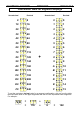
PARAMETERS ADJUSTMENT AT FULL SPEED (2/3)
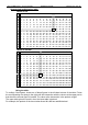
IV. Adjustment of the direct approach precision
At address 00E, segment 5 should be on.
1) Select address 22, with the little left-hand red switch in the RAM (upper) position,
and send the lift to the bottom floor. The tape head may show a positive value
e.g. 09 (i.e. 9 impulses x 2mm = 18mm), which means that the car has stopped
18mm above floor level.
Increase the value programmed at address 008 (DV2) by this 18mm.
If the lift stops after floor level, reduce the value programmed at address 008 (DV2)
by these 18mm.
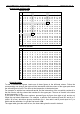
V. Automatic adjustment of the hysterisis zone
This must be done if the lowest level is not the main floor.
1) Position the lift above the ED magnets.
2) With the left-hand switch of the BG17 communication tool on PAR, programme
10 at address E0.
3) Send the car up one floor and then down one floor, so that the tape-head passes
the ED magnets in both directions.
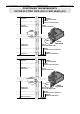
VI. Positioning of EM magnet at top floor
Position the EM magnet at the slow-down point for the top floor, this may be useful
if the lift does not cross the bottom magnets very often.
To carry out this operation, you will need the following elements:
• An O03-2 tape-head.
• An N70 interface board for an O03-2 tape-head.
• A pair of magnets to position as shown on page 11.
1) During normal operation, when the lift stops exactly at the desired floor, send the
lift up to the top floor and position the EM magnets to obtain the desired slow-
down distance (the position of the EM magnets is roughly the same as that of the
ED magnets).
2) If afterwards when coming back to the top floor, the lift does not stop at floor
level, move the EM magnets to the value corresponding to the reset heigt.