Rhein Tech Laboratories 360 Herndon Parkway Suite 1400 Herndon, VA 20170 http://www.rheintech.com APPENDIX E: MANUAL Please see the following pages. Client: Ohmart/VEGA Model: VEGAPULS 68 FCC ID: MOIPULS68 Standards: FCC 15.
Operating Instructions VEGAPULS 68 4 ...
Contents Contents 1 About this document 1.1 Function . . . . . . . . . . . . . . . . . . . . . . . . . 1.2 Target group . . . . . . . . . . . . . . . . . . . . . . 1.3 Symbolism used. . . . . . . . . . . . . . . . . . . . 4 4 4 2 For 2.1 2.2 2.3 2.4 2.5 2.6 2.7 2.8 2.9 6 6 6 6 7 7 8 8 8 your safety Authorised personnel . . . . . . . . . . . . . Appropriate use . . . . . . . . . . . . . . . . . Warning about misuse . . . . . . . . . . . . General safety instructions . . . . . . . . . CE conformity . . .
Contents 6 Setup with the indicating and adjustment module PLICSCOM 6.1 Short description . . . . . . . . . . . . . . . . . 6.2 Installing the indicating and adjustment module PLICSCOM . . . . . . . . . . . . . . . 6.3 Adjustment system . . . . . . . . . . . . . . . . 6.4 Setup procedure . . . . . . . . . . . . . . . . . 6.5 Menu schematic. . . . . . . . . . . . . . . . . . . . 31 .. .. .. .. 31 33 34 39 7 Setup with PACTware™ 7.1 Connecting the PC . . . . . . . . . . . . . . . . . . 42 7.
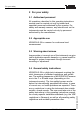
About this document 1 About this document 1.1 Function This operating instructions manual has all the information you need for quick setup and safe operation of VEGAPULS 68. Please read this manual before you start setup. 1.2 Target group This operating instructions manual is directed to trained personnel. The contents of this manual should be made available to these personnel and put into practice by them. 1.3 Symbolism used Information, tip, note This symbol indicates helpful additional information.
About this document Sequence Numbers set in front indicate successive steps in a procedure. 29261-EN-050202 1 VEGAPULS 68 - 4 ...
For your safety 2 For your safety 2.1 Authorised personnel All operations described in this operating instructions manual must be carried out only by trained and specialist personnel authorised by the operator. For safety and warranty reasons, any internal work on the instruments must be carried out only by personnel authorised by the manufacturer. 2.2 Appropriate use VEGAPULS 68 is a sensor for continuous level measurement. 2.
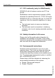
For your safety 2.5 CE conformity VEGAPULS 68 is in CE conformity with EMC (89/336/ EWG), fulfils the Namur recommendation NE 21 and is in CE conformity with NSR (73/23/EWG). Conformity has been judged acc. to the following standards: l l EMC: - Emission EN 61326: 1997 (class B) - Susceptibility EN 61326: 1997/A1: 1998 NSR: EN 61010-1: 2001. 2.6 Compatibility acc. to NAMUR NE 53 VEGAPULS 68 meets NAMUR recommendation NE 53.
For your safety 2.7 FCC conformity (only for USA/Canada) VEGAPULS with all antenna versions are FCC approved. Modifications must be expressively agreed by VEGA, otherwise the operating licence acc. to FCC will expire. VEGAPULS 68 is in conformity with part 15 of the FCC regulations. Note the respective regulations for operation: l l The instrument must not cause any interfering emissions The instrument must be insensitive to interfering emissions, also to such causing unwanted operating conditions. 2.
Product description 3 Product description 3.
Product description 1 2 3 4 Fig. 1: VEGAPULS 68 with horn antenna and swivelling holder 1 2 3 4 Housing cover with integrated PLICSCOM (optional) Housing with electronics Swivelling holder with flange Horn antenna 3.2 Principle of operation Area of application VEGAPULS 68 is a radar sensor in K-band technology for continuous level measurement. A version of VEGAPULS 68 is available for the respective application: l l VEGAPULS 68 - 4 ...
Product description Physical principle The antenna of the radar sensor emits short radar pulses with a duration of approx. 1 ns. These pulses are reflected by the product and received by the antenna as echoes. The running time of the radar pulses from emission to reception is proportional to the distance and hence to the level. The determined level is converted into an appropriate output signal and outputted as measured value. Power supply Two-wire electronics 4 ...
Product description Storage and transport temperature l l Storage and transport temperature see Supplement, Technical data, Ambient conditions Relative humidity 20 ... 85 % 29261-EN-050202 12 VEGAPULS 68 - 4 ...
Mounting 4 Mounting 4.1 General instructions Installation position Select an installation position you can easily reach for mounting and connecting as well as later retrofitting of an indicating and adjustment module PLICSCOM. The housing can be rotated by 330° without the use of any tools. You can also install the indicating and adjustment module PLICSCOM in four different positions (each displaced by 90°).
Mounting 1 2 3 4 100% 0% Fig. 3: Measuring range (operating range) and max. measuring distance 1 2 3 Pressure full empty (max. measuring distance) Measuring range The process fitting must be sealed with gauge or low pressure in the vessel. Check before use, if the seal material is resistant against the measured product. The max. permissible pressure is stated in the Technical data in the Supplement or on the type label of the sensor. 4.
Mounting 3 Insert the antenna from below into the vessel socket and secure it against falling off 4 Retighten the antenna with hexagon screws (1) to the antenna socket; torque max. 10 Nm (7.5 lbf ft) 1 2 Fig. 4: Dismounting of the horn antenna 1 2 Hexagon screws on the antenna socket Antenna 4.
Mounting 5 Remove the parabolic antenna (4) axially 6 Mount sensor flange to the adapter flange and clamp it 7 Check if there is a O-ring seal on the adapter and if it is not damaged. If necessary, replace it: Viton, article no. 2.28248, Kalrez 6375 article no. 2.27351. 8 Remount the parabolic antenna (4) 9 Tighten compression nut (3) with SW 41, torque max. 50 Nm. 10 Tighten locknut (2) with SW 36, torque max. 40 Nm. 1 2 3 4 Fig.
Mounting Installation location When mounting the sensor, keep a distance of at least 200 mm (7.9 in) to the vessel wall. If the sensor is installed in the center of concave or arched vessel tops, multiple echoes can arise. These can, however, be faded out by an appropriate adjustment (see Setup). If this distance cannot be maintained, a false echo storage should be carried out during setup. This applies particularly if buildup on the vessel wall is expected.
Mounting Fig. 7: Vessel with conical bottom Inflowing material Do not mount the instruments in or above the filling stream. Make sure that you detect the product surface and not the inflowing product. Fig. 8: Inflowing material Mounting boss PreferablyVEGAPULS 68 should be mounted without socket flush to the vessel top. 29261-EN-050202 18 VEGAPULS 68 - 4 ...
ca. 10 mm Mounting Fig. 9: Recommended socket mounting h max. If the reflective properties of the medium are good, you can mount VEGAPULS 68 on a socket piece. The socket end should be smooth and burr-free, if possible also rounded. Carry out a false echo storage. d d 1½" 50 mm/2" 80 mm/3" 100 mm/4" 150 mm/6" h max. 200 mm 250 mm 300 mm 500 mm 800 mm Fig. 10: Deviating socket dimensions In liquids, direct the sensor as close as vertical to the product surface to achieve optimum measurement results.
Mounting Fig. 11: Orientation in liquids The version with swivelling holder ensures optimum orientation of the sensor to the solid cone. Loosen the screw on the swivelling holder with a flat wrench SW 13, direct the sensor and retighten the screw, torque max. 20 Nm. Vessel installations The radar sensor should be installed at a location where no installations cross the radar signals. Vessel installations such as, for example, ladders, limit switches, heating spirals, struts, etc.
Mounting Material heaps Large material heaps are detected with several instruments, which can be mounted on e.g. traverse cranes. For this type of application, it is best to orient the sensor toward the solid surface. 29261-EN-050202 Fig. 13: Radar sensors on traverse crane VEGAPULS 68 - 4 ...
Connecting to power supply 5 Connecting to power supply 5.1 Preparing the connection Note safety instructions Always observe the following safety instructions: l l Connect only in the complete absence of line voltage If overvoltages are expected, overvoltage arresters should be installed. Tip: We recommend VEGA overvoltage arresters ÜS-F-LB-I and ÜSB 62-36G.X.
Connecting to power supply Cable screening and grounding Connect the cable screen on both ends to ground potential. In the sensor, the screen must be connected directly to the internal ground terminal. The ground terminal outside on the housing must be connected to the potential equalisation (low impedance). If potential equalisation currents are expected, the connection on the evaluation side must be made via a ceramic capacitor (e.g. 1 nF, 1500 V).
Connecting to power supply 9 Check the hold of the wires in the terminals by lightly pulling on them 10 Connect the screen to the internal ground terminal and the external ground terminal to potential equalisation 11 Tighten the compression nut of the cable entry, the seal ring must completely encircle the cable 12 Screw the housing cover back on The electrical connection is finished. Fig. 14: Connection steps 6 and 7 5.
Connecting to power supply Housing overview 4 4 1 4 2 3 Fig. 15: Material versions, single chamber housing 1 2 3 4 Plastic Aluminium Stainless steel Filter element for pressure compensation Electronics and connection compartment Display Com. 4 1 2 5 6 7 8 1 2 3 Fig. 16: Electronics and connection compartment, single chamber housing 1 2 29261-EN-050202 3 4 Plug connector for VEGACONNECT (I²C interface) Spring-loaded terminals for connection of the ext.
Connecting to power supply Wiring plan Display Com. 1 2 5 6 7 8 1 Fig. 17: Wiring plan, single chamber housing 1 Power supply/Signal output 5.4 Wiring plans, double chamber housing The following illustrations apply to the non-Ex as well as to the Ex ia version. The Exd version is described in the next subchapter. Housing overview 1 2 3 5 4 Fig.
Connecting to power supply Electronics compartment 1 Display Com. 1 2 5 6 7 8 2 3 Fig. 19: Electronics compartment, double chamber housing 1 2 3 Plug connector for VEGACONNECT (I²C interface) Internal connection cable to the connection compartment Terminals for VEGADIS 61 Display Connection compartment 1 3 1 2 Com. 2 Fig.
Connecting to power supply Wiring plan Com. 1 2 1 Fig. 21: Connection compartment, double chamber housing 1 Power supply/Signal output 5.5 Wiring plans, double chamber housing Exd Housing overview 1 2 3 5 4 Fig. 22: Double chamber housing 1 2 3 4 5 Housing cover, connection compartment Blind stopper or plug M12x1 for VEGADIS 61 (option) Housing cover, electronics compartment Filter element for pressure compensation Cable entry or plug 29261-EN-050202 28 VEGAPULS 68 - 4 ...
Connecting to power supply Electronics compartment 1 Display Com. 1 2 5 6 7 8 2 3 Fig. 23: Electronics compartment, double chamber housing 1 2 3 Plug connector for VEGACONNECT (I²C interface) Internal connection cable to the connection compartment Terminals for VEGADIS 61 Connection compartment 1 1 2 2 Fig.
Connecting to power supply Wiring plan 1 2 1 Fig. 25: Wiring plan, double chamber housing Exd 1 Power supply/Signal output 29261-EN-050202 30 VEGAPULS 68 - 4 ...
Setup with the indicating and adjustment module PLICSCOM 6 Setup with the indicating and adjustment module PLICSCOM 6.1 Short description Function/Configuration The indicating and adjustment module PLICSCOM is used for measured value display, adjustment and diagnosis.
Setup with the indicating and adjustment module PLICSCOM PLICSCOM is powered by the sensor, an additional connection is not necessary. Fig. 26: Installation of PLICSCOM Note: If you intend to retrofit VEGAPULS 68 with PLICSCOM for continuous measured value indication, a higher cover with an inspection glass is required. 29261-EN-050202 32 VEGAPULS 68 - 4 ...
Setup with the indicating and adjustment module PLICSCOM 6.3 Adjustment system 2 1 1.1 3 Fig.
Setup with the indicating and adjustment module PLICSCOM ed. Any values not confirmed with [OK] will not be saved. 6.4 Setup procedure Switch on phase After VEGAPULS 68 is connected to power supply or after voltage recurrence, the instrument carries out a self-test for approx. 30 seconds. The following steps are carried out: internal check of the electronics indication of the instrument type, the firmware version as well as the sensor TAGs (sensor name) l Output signal jumps briefly (approx.
Setup with the indicating and adjustment module PLICSCOM entered values. At the same time, the operating range of the sensor is limited from maximum range to the requested range. The real product level during this adjustment is not important, because the min./max. adjustment is always carried out without changing the product level. These settings can be made ahead of time without the instrument having to be installed.
Setup with the indicating and adjustment module PLICSCOM 5 Save the settings with [OK] and move to max. adjustment with [–>]. Carrying out max. adjustment Proceed as follows: Max. adjustment 100.00 % = 1.000 m(d) 2.000 m(d) 1 Prepare the percentage value for editing with [OK] and set the cursor to the requested position with [–>]. Set the requested percentage value with [+] and save with [OK]. The cursor jumps now to the distance value.
Setup with the indicating and adjustment module PLICSCOM Enter the requested parameter via the respective keys, save your settings and jump to the next menu item with the [–>] key. Vessel form Apart from the medium also the vessel form can influence the measurement. To adapt the sensor to these conditions, this menu item offers (depending on either liquid or solid is selected) different options. For Liquid these are Storage tank, Stilling tube, Open vessel or Stirred vessel, for Solid Silo or Bunker.
Setup with the indicating and adjustment module PLICSCOM appropriate curve, the volume percentage of the vessel is displayed correctly. If the volume should not be displayed in percent but e.g. in l or kg, a scaling can be set in the menu item Display. Linearization curve linear Enter the requested parameter via the respective keys, save your settings and jump to the next menu item with the [–>] key. Sensor-TAG In this menu item you can enter an unambiguous designation for the sensor, e.g.
Setup with the indicating and adjustment module PLICSCOM 1 Move from the measured value display to the main menu by pushing [OK]. 2 Select the menu item Service with [–>] and confirm with [OK]. Now the menu item false echo storage is displayed. 3 Confirm False echo storage - Change now with [OK] and select in the below menu Create new. Enter the actual distance from the sensor to the product surface. All false echoes in this area are detected by the sensor and saved after confirming with [OK].
Setup with the indicating and adjustment module PLICSCOM 6.5 Menu schematic Basic adjustment > Basic adjustment Display Diagnostics Service Info 1 Min. adjustment 0.00 % = 4.000 m(d) 3.000 m(d) 1.1 Damping 1.5 Max. adjustment 100.00 % = 1.000 m(d) 2.000 m(d) 1.2 Linearization curve 1.6 0s Medium Solid 1.3 Vessel form 1.4 Silo Sensor-TAG linear 1.7 Sensor Display > Basic adjustment Display Diagnostics Service Info Displayed value 2 2.1 scaled Display units 2.
Setup with the indicating and adjustment module PLICSCOM Service > Basic adjustment Display Diagnostics Service Info False echo storage 4 4.1 Addl. adjustments 4.2 none 4.5 Units of measurement Reset select? Copy sensor data 4.6 m(d) select? 4.9 PIN Copy sensor data? 4.3 Output mode 4-20 mA Failure mode <3.6 mA min. current 3.8 mA Change? Reset Current output Language Simulation 4.4 Simulation start? 4.7 Deutsch HART mode 4.8 Standard Address 0 4.
Setup with PACTware™ 7 Setup with PACTware™ 7.1 Connecting the PC Connecting the PC directly to the sensor VEGACONNECT 3 PACTwareTM/ 3 >PA< 1 = ~ 2 Power supply Fig. 28: Connecting the PC directly to the sensor 1 2 3 RS232 connection VEGAPULS 68 I²C adapter cable for VEGACONNECT 3 Necessary components: l l l l VEGAPULS 68 PC with PACTware™ and suitable VEGA-DTM VEGACONNECT 3 with I²C adapter cable (article no. 2.27323) power supply unit 29261-EN-050202 42 VEGAPULS 68 - 4 ...
Setup with PACTware™ Connecting the PC to the signal cable = 4 ~ 2 Power supply 3 PACTwareTM/ VEGACONNECT 3 1 Fig. 29: Connecting the PC to the signal cable 1 2 3 4 RS232 connection VEGAPULS 68 HART adapter cable for VEGACONNECT 3 HART resistance 250 Ohm Necessary components: l l l l l VEGAPULS 68 PC with PACTware™ and suitable VEGA-DTM VEGACONNECT 3 with HART adapter cable (art. no. 2.25397) HART resistance approx.
Setup with PACTware™ from our homepage. A detailed description is available in the online help of PACTware™ and the VEGA-DTMs. Note: Keep in mind that for setup of VEGAPULS 68, DTMCollection 04/2004 or a newer version should be applied. All currently available VEGA-DTMs are provided in the DTM Collection on CD and can be bought from the responsible VEGA agency for a token fee. This CD includes also the up-to-date PACTware™ version. The basic version of this DTM Collection incl.
Maintenance and fault rectification 8 Maintenance and fault rectification 8.1 Maintenance When used as directed in normal operation, VEGAPULS 68 is completely maintenance-free. 8.2 Fault rectification Causes of failure VEGAPULS 68 offers maximum reliability. Nevertheless, faults may occur during operation. These can have the following causes, e.g.: l l l l Sensor Process Power supply Signal processing.
Maintenance and fault rectification ? 4 ... 20 mA signal missing l incorrect connection to power supply à check connection acc. to chapter "Connection procedure" and correct, if necessary, acc. to chapter "Wiring plans" l no power supply à check cables for line break, repair, if necessary l supply voltage too low or load resistance too high à check and adapt, if necessary ? Current signal greater than 22 mA or less than 3.
Maintenance and fault rectification ? E036 l no operable sensor software à carry out a software update or return instrument for repair ? E041 l hardware error, electronics defective à exchange instrument or return it for repair 8.3 Exchanging the oscillator Preparations If the electronics module is defective, it can be replaced by the user Oscillator PS-E.60SH. is suitable for VEGAPULS 68 – 4 ... 20 mA/HART. The following versions are available: l l PS-E.60SHX (without approvals) PS-E.
Maintenance and fault rectification Exchange Proceed as follows: 1 Switch off power supply 2 Unscrew the housing cover 3 Lift the opening levers of the terminals with a screwdriver 4 Pull the connection cables out of the terminals 5 Loosen the two screws with a Phillips screwdriver (size 1) 1 2 Fig. 30: Loosen the screws 1 2 Electronics module Screws (2 pcs.) 6 Pull the existing oscillator out by holding the opening levers. 7 Compare the new oscillator with the old one.
Maintenance and fault rectification 11 Close the opening levers of the terminals, you will hear the terminal spring closing 12 Check the hold of the wires in the terminals by lightly pulling on them 13 Check the tightness of the cable entry. The seal ring must completely encircle the cable. 14 Screw the housing cover back on The electronics exchange is finished. As a rule, the exchange of the oscillator must be documented internally when used in Ex applications.
Maintenance and fault rectification By doing this you help us carry out the repair quickly and without having to call for additional information. l l l l Print and fill out one form per instrument Clean the instrument and pack it damage-proof Attach the completed form and possibly also a safety data sheet to the instrument Send the instrument to the respective address of your agency. In Germany to the VEGA headquarters in Schiltach. 29261-EN-050202 50 VEGAPULS 68 - 4 ...
Dismounting 9 Dismounting 9.1 Dismounting procedure Warning: Before dismounting, be aware of dangerous process conditions such as e.g. pressure in the vessel, high temperatures, corrosive or toxic products etc. Take note of chapters "Mounting" and "Connecting to power supply" and carry out the listed steps in reverse order. 9.2 Disposal VEGAPULS 68 consists of materials which can be recycled by specialised recycling companies. We have purposely designed the electronic modules to be easily separable.
Supplement 10 Supplement 10.1 Technical data General data Materials, non-wetted parts - housing - seal ring between housing and housing cover - inspection window in housing cover for PLICSCOM - ground terminal Materials, wetted parts - process fitting - Antenna - seal, antenna system Weight with horn antenna - process fitting, thread - process fitting, flange - process fitting swivelling holder with flange Weight with parabolic antenna - process fitting, thread - process fitting, flange 52 stainless steel 1.
Supplement Output variable Output signal Resolution Fault signal Current limitation Load Integration time (63% of the input variable) Rise time Fulfilled Namur recommendation 4 ... 20 mA/HART 1.6 µA current output unchanged, 20.5 mA, 22 mA, < 3.6 mA (adjustable) 22 mA see load diagram in Power supply 0 ... 999 s, adjustable 150 ms (ti: 0 s, 0 ... 100 %) NE 43 Input variable Parameter Min. distance from antenna end max. measuring range distance between process fitting and product surface 400 mm (15.
Supplement > 4 s (dependent on the parameter adjustment) Received average emitted power reaching an object directly in front of the antenna - distance 1 m 108 nW per cm² (108 x 10-9 W/cm²) - distance 5 m 4.3 nW per cm² (4,3 x 10⁻⁹ W/cm²) Beam angle with horn antenna, depending on the antenna diameter - ø 40 mm 22° - ø 48 mm 18° - ø 75 mm 10° - ø 95 mm 8° Beam angle with parabolic antenna Accuracy 3.5 ° see diagram 30 mm 15 mm 1,0 m 70 m -15 mm -30 mm Fig.
Supplement Process conditions Vessel pressure horn antenna - without swivelling holder -1 ... 40 bar (-100 ... 4000 kPa or -14.5 ... 580) -1 ... 1 bar (-100 ... 100 kPa or -14.5 ... 14.5 psi) not sealing - with swivelling holder vessel pressure parabolic antenna - without swivelling holder - with swivelling holder -1 ... 6 bar (-100 ... 4000 kPa or -14.5 ... 87 psi) -1 ... 1 bar (-100 ... 100 kPa or -14.5 ... 14.
Supplement Electromechanical data Cable entry/plug5) - single chamber housing l or: l 1x cable entry M20x1.5 (cable-ø 5 … 9 mm), 1x blind stopper M20x1.5 1 x closing cap ½ NPT, 1 x blind stopper ½ NPT or: l - double chamber housing l or: l 1x plug (depending on the version), 1x blind stopper M20x1.5 1 x cable entry M20x1.5 (cable-ø 5 … 9 mm), 1 x blind stopper M20x1.
Supplement Materials - housing - inspection window ABS Polyester foil Power supply Supply voltage - non-Ex instrument - EEx ia instrument - EExd ia instrument 15 ... 36 V DC (14 ... 36 V with VEGAMET) 15 ... 30 V DC (14 ... 30 V with VEGAMET) 20 ... 36 V DC Permissible residual ripple - < 100 Hz - 100 Hz ... 10 kHz Uss < 1 V Uss < 10 mV Load see diagram Ω 1000 750 3 500 2 1 250 4 15 16 18 20 22 24 26 28 30 32 34 36 V Fig.
Supplement Approvals6) ATEX 7) ATEX II 1G, 1/2G, 2G EEx ia IIC T5; ATEX II 1/2G, 2G EEx d ia IIC T5; ATEX II 1/2D IP6X T IEC EEx ia IIC T5 IEC 7) 58 Deviating data with Ex applications: see separate safety instructions depending on order specification VEGAPULS 68 - 4 ...
Supplement 10.2 Dimensions Housing ~ 87mm (3 27/64") ø 84mm /16") ø 77mm ~ 116mm (4 9/16") ø 84mm (3 5/16") 114mm (4 31/64") ø 77mm (3 1/32") 117mm (4 39 120mm (4 23/32") ~ 69mm (2 23/32") 112mm (4 13/32") ~ 69mm (2 23/32") 20x1,5 ½ ½ NPT 1 ½ NPT 2 M20x1,5/ ½ NPT 3 4 29261-EN-050202 Fig. 33: Housing versions (with integrated PLICSCOM the height of the housing increases by 9 mm/0.
Supplement 118mm (4 41/64") 46mm (1 13/16") 2 y G1½A / 1½ NPT mm y x 1½" 100 ø40 2" 120 ø48 3" 216 ø75 4" 430 ø95 22mm (55/64") 1 22mm (55/64") 38mm (1 1/2") VEGAPULS 68 with horn antenna in threaded version x y 1½" 3 15/16" 4 23/32" 8 1/2" 16 59/64" 2" 3" 4" x y inch ø1 37/64" ø1 57/64" ø2 61/64" ø3 47/64" x Fig. 34: VEGAPULS 68 with horn antenna in threaded version 1 Standard 2 with temperature adapter 29261-EN-050202 60 VEGAPULS 68 - 4 ...
Supplement 118mm (4 41/64") 46mm (1 13/16") 2 mm y x 1½" 100 ø40 2" 120 ø48 3" 216 ø75 4" 430 ø95 inch y x 1½" 3 15/16" 4 23/32" 8 1/2" 16 59/64" ø1 37/64" ø1 57/64" ø2 61/64" ø3 47/64" 2" x 3" 4" y y G1½A / 1½ NPT 22mm (55/64") 38mm (1 1/2") 1 22mm (55/64") VEGAPULS 68 with horn antenna in threaded version with purging air connection x 29261-EN-050202 Fig.
Supplement 118mm (4 41/64") 2 mm y x 1½" > 180 ø40 2" > 200 ø48 3" > 296 ø75 4" > 630 ø95 inch y 1½" 7 3/32" 7 7/8" 11 21/32" 24 51/64" 2" 3" 4" x ø1 37/64" ø1 57/64" ø2 61/64" ø3 47/64" y y G1½A / 1½ NPT 22mm (55/64") 38mm (1 1/2") 1 46mm (1 13/16") 22mm (55/64") VEGAPULS 68 with horn antenna in threaded version with purging air connection and antenna extension x x Fig.
Supplement y b 2 140mm (5 33/64") d 1 60mm (2 23/64") VEGAPULS 68 with horn antenna in flange version x k D mm inch D b k d x y D b DN 40 PN 40 150 18 110 4xø18 40 100 DN 40PN 40 5 29/32" 45/64" 4 21/64" 4xø45/64" 1 37/64" 3 15/16" DN 50 PN 40 165 20 125 4xø18 48 120 DN 50 PN 40 6 1/2" 25/32" 4 59/64" 4xø45/64" 1 57/64" 4 23/32" DN 80 PN 40 200 24 160 8xø18 75 216 DN 80 PN 40 7 7/8" 15/16" 6 19/64" 8xø45/64" 2 61/64" 25/32" 7 3/32" 3 47/64" 16 59/64"
Supplement VEGAPULS 68 with horn antenna and swivelling holder 2 40mm (1 37 /64 ") 1 D x y x 1½" 100 ø40 2" 120 ø48 3" 216 ø75 4" 430 ø95 inch y x 1½" 2" 3" 3 15/16" 4 23/32" 8 1/2" 16 59/64" ø1 37/64" ø1 57/64" ø2 61/64" ø3 47/64" 4" 20mm ( 25/ 32 ") mm y y 20mm ( 25/ 32 ") b 120m m (4 2 3/ 32 ") k x mm D b k d inch D b k d DN 50 / 2" 165 11,5 122,8 4xø19 DN 50 / 2" 6 1/2" 29/64" 4 53/64" 4xø3/4" DN 80 / 3" 200 11,5 156,2 4xø21 DN 80 / 3" 7 7/
Supplement 120m m (4 2 3/ 32 ") VEGAPULS 68 with horn antenna, swivelling holder and purging air connection b d k y 20mm ( 25/ 32 ") D x y x inch y 1½" 100 ø40 1½" 3 15/16" 2" 120 ø48 2" 3" 216 ø75 3" 4" 430 ø95 4" x ø1 37/64" 4 23/34" ø1 57/64" ø2 61/64" 8 1/2" 16 59/64" ø3 47/64" mm D b k d inch D b k d DN 50 / 2" 165 11,5 122,8 4xø19 DN 50 / 2" 6 1/2" 29/64" 4 53/64" 4xø3/4" 29/64" 6 5/32" 4xø53/64" 29/64" 7 3/16" 8xø55/64" DN 80 / 3" 200 11,
Supplement 120m m (4 2 3/ 32 ") VEGAPULS 68 with horn antenna, swivelling holder, purging air connection and antenna extension b d k y 20mm ( 25/ 32 ") D mm y x inch y 1½" > 180 ø40 1½" 7 3/32" 2" > 200 ø48 3" > 296 ø75 2" 3" 4" > 630 ø95 4" x ø1 37/64" 7 7/8" ø1 57/64" 11 21/32" ø2 61/64" 24 51/64" ø3 47/64" mm D b k d inch D b k d DN 50 / 2" 165 11,5 122,8 4xø19 DN 50 / 2" 6 1/2" 29/64" 4 53/64" 4xø3/4" DN 80 / 3" 200 11,5 156,2 4xø21 DN 80 / 3"
Supplement 128mm (5 3/64") G1½A / 1½ NPT 118mm (4 41/64") 46mm (1 13/16") 2 22mm (55/64") 38mm (1 1/2") 1 22mm (55/64") VEGAPULS 68 with parabolic antenna in threaded version ø 243mm (9 9/16") 29261-EN-050202 Fig. 41: VEGAPULS 68 with parabolic antenna in threaded version 1 Standard 2 with temperature adapter VEGAPULS 68 - 4 ...
Supplement VEGAPULS 68 with parabolic antenna in flange version 2 b k 140mm (5 33/64") D 60mm (2 23/64") 1 128mm (5 3/64") d ø 243mm (9 9/16") mm inch D b k d D b DN 40 PN 40 150 18 110 4xø18 DN 40PN 40 5 29/32" 45/64" k DN 50 PN 40 165 20 125 4xø18 DN 50 PN 40 6 1/2" 25/32" 4 59/64" 4xø45/64" DN 80 PN 40 200 24 160 8xø18 DN 80 PN 40 7 7/8" 15/16" 6 19/64" 8xø45/64" DN 100 PN 16 220 20 180 8xø18 DN 100 PN 16 8 21/32" 25/32" 7 3/32" DN 150 PN 16 285 22
Supplement VEGAPULS 68 with parabolic antenna and swivelling holder 2 40mm (1 37 /64 ") 1 D 140m m (5 3 3/ 64 ") b 120m m (4 2 3/ 32 ") k ø 243 mm (9 9/ 16 ") mm D b k d inch D b k d DN 50 / 2" 165 11,5 122,8 4xø19 DN 50 / 2" 6 1/2" 29/64" 4 53/64" 4xø3/4" 7 7/8" DN 80 / 3" 200 11,5 156,2 4xø21 DN 80 / 3" DN 100 / 4" 220 11,5 182,5 4xø22 DN 100 / 4" 8 21/32" 29/64" 6 5/32" 4xø53/64" 29/64" 7 3/16" 8xø55/64" 29261-EN-050202 Fig.
10.3 CE declaration of conformity 29261-EN-050202 Fig. 44: CE declaration of conformity 70 VEGAPULS 68 - 4 ...
29261-EN-050202 VEGAPULS 68 - 4 ...
VEGA Grieshaber KG Am Hohenstein 113 77761 Schiltach Germany Phone +49 7836 50-0 Fax +49 7836 50-201 E-mail: info@de.vega.com www.vega.com ISO 9001 All statements concerning scope of delivery, application, practical use and operating conditions of the sensors and processing systems correspond to the information available at the time of printing.