
User Manual


Contents
1 About this document
1.1 Function. . . . . . . . . . . . . . . . . . . . . . . . . . . . . . . . . .
4
1.2 Target group . . . . . . . . . . . . . . . . . . . . . . . . . . . . . .
4
1.3 Symbolism used. . . . . . . . . . . . . . . . . . . . . . . . . . . .
4
2 For your safety
2.1 Authorised personnel . . . . . . . . . . . . . . . . . . . . . . . .
5
2.2 Appropriate use . . . . . . . . . . . . . . . . . . . . . . . . . . . .
5
2.3 Warning about misuse . . . . . . . . . . . . . . . . . . . . . . .
5
2.4 General safety instructions . . . . . . . . . . . . . . . . . . . .
5
2.5 CE conformity . . . . . . . . . . . . . . . . . . . . . . . . . . . . .
6
2.6 Fulfillment of NAMUR recommendations . . . . . . . . . .
6
2.7 Radio approval for Europe . . . . . . . . . . . . . . . . . . . .
6
2.8 Radio approval for USA/Canada . . . . . . . . . . . . . . . .
6
2.9 Environmental instructions. . . . . . . . . . . . . . . . . . . . .
6
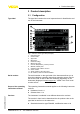
3 Product description
3.1 Configuration . . . . . . . . . . . . . . . . . . . . . . . . . . . . . .
7
3.2 Principle of operation . . . . . . . . . . . . . . . . . . . . . . . .
8
3.3 Packaging, transport and storage . . . . . . . . . . . . . . .
8
3.4 Accessories and replacement parts . . . . . . . . . . . . . .
9
4 Mounting
4.1 General instructions . . . . . . . . . . . . . . . . . . . . . . . . .
11
4.2 Mounting preparations - Horn antenna . . . . . . . . . . . .
11
4.3 Mounting preparations - Parabolic antenna. . . . . . . . .
12
4.4 Mounting instructions . . . . . . . . . . . . . . . . . . . . . . . .
13
5 Connecting to power supply
5.1 Preparing the connection . . . . . . . . . . . . . . . . . . . . .
25
5.2 Connection. . . . . . . . . . . . . . . . . . . . . . . . . . . . . . . .
26
5.3 Wiring plan, single chamber housing . . . . . . . . . . . . .
28
5.4 Wiring plan, double chamber housing . . . . . . . . . . . .
28
5.5 Wiring plan with double chamber housing Ex d . . . . .
29
5.6 Wiring plan - version IP 66/IP 68, 1 bar . . . . . . . . . . .
30
5.7 Switch on phase. . . . . . . . . . . . . . . . . . . . . . . . . . . .
30
6 Set up with the indicating and adjustment module
6.1 Insert indicating and adjustment module. . . . . . . . . . .
31
6.2 Adjustment system . . . . . . . . . . . . . . . . . . . . . . . . . .
32
6.3 Parameter adjustment. . . . . . . . . . . . . . . . . . . . . . . .
33
6.4 Saving the parameter adjustment data . . . . . . . . . . . .
41
7 Setup with PACTware
7.1 Connecting the PC . . . . . . . . . . . . . . . . . . . . . . . . . .
42
7.2 Parameter adjustment with PACTware . . . . . . . . . . . .
43
7.3 Saving the parameter adjustment data . . . . . . . . . . . .
44
2 VEGAPULS 62 • 4 … 20 mA/HART two-wire
Contents
36503-EN-100607