Operating Instructions Overvoltage arrester B61-300 Document ID: 40488 Separating and protective instruments
Contents Contents 1 About this document 1.1 1.2 1.3 2 . . . . . . . . . . . . . . . . . . . . . . . . . . . . . . . . . . . . . . . . . . . . . . . . . . . . . . . . . . . . . . . . . . . . . . . . . . . . . . . . . . . . . . . . .. .. .. .. .. .. .. .. 4 4 4 4 4 5 5 5 Structure . . . . . . . . . . . . . . . . . . Principle of operation . . . . . . . . . Packaging, transport and storage Installation in switching cabinet . . Mounting in housing . . . . . . . . . . . . . . . . . . . . . .
1 About this document 1 About this document 1.1 Function This operating instructions manual provides all the information you need for mounting, connection and setup as well as important instructions for maintenance and fault rectification. Please read this information before putting the instrument into operation and keep this manual accessible in the immediate vicinity of the device. 1.2 Target group This operating instructions manual is directed to trained qualified personnel.
2 For your safety 2 For your safety 2.1 Authorised personnel All operations described in this operating instructions manual must be carried out only by trained specialist personnel authorised by the plant operator. During work on and with the device the required personal protective equipment must always be worn. 2.2 Appropriate use The B61-300 is an overvoltage arrester for sensors and signal conditioning instruments with mains voltage supply.
2 For your safety 2.6 CE conformity This device fulfills the legal requirements of the applicable EC guidelines. By attaching the CE mark, VEGA provides a confirmation of successful testing. You can find the CE conformity declaration in the download area of www.vega.com. 2.7 Safety instructions for Ex areas Please note the Ex-specific safety information for installation and operation in Ex areas. These safety instructions are part of the operating instructions manual and come with the Ex-approved instruments.
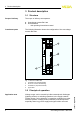
3 Product description 3 Product description 3.1 Structure Scope of delivery The scope of delivery encompasses: l l Constituent parts Overvoltage arrester B61-300 Documentation - this operating instructions manual The following illustration shows the configuration of the overvoltage arrester B61-300: PE OUT N B61 - 300 L1 2 max. 300 V AC/16 A IP 20 4 1 3 L1 N IN PE Fig.
3 Product description Such voltage surges can cause damage to sensors and signal conditioning instruments. VEGA overvoltage arresters reduce voltage surges on the supply or signal cables to a safe level. They are designed for mounting on carrier rail according to EN 50 022/EN 50 035 in the switching cabinet or in a metal or plastic housing close to the sensor. Functional principle Depending on the version, different combinations of protective elements for voltage limitation are used.
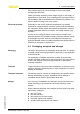
3 Product description Storage and transport temperature l l Storage and transport temperature see chapter "Supplement Technical data - Ambient conditions" Relative humidity 20 … 85 % 40488-EN-110527 8 Overvoltage arrester • B61-300
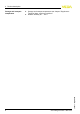
3 Product description 3.4 Installation in switching cabinet The overvoltage arrester is mounted in the switching cabinet on carrier rails according to EN 50 022 (DIN rail) or EN 50 035 (C-rail). It is fastened to the carrier rail with a screw located on its exterior. The screw is marked with the symbol for functional ground. Depending on the version, it may be galvanically connected to the ground terminal of the overvoltage arrester (see circuit diagram in chapter "Wiring plan").
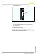
3 Product description 1 Loosen fixing screw OUT 1 IP 20 IN Fig. 4: Mounting on carrier rail 1 Fixing screw 2 Place the overvoltage arrester onto the rail and let it snap in 3 Tighten fixing screw 3.5 Mounting in housing The overvoltage arrester is optionally available in a plastic or aluminium housing. Make sure when mounting that the cable glands point downward. Thus avoids water ingress.
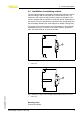
3 Product description The carrier rail inside the housing is galvanically connected to the ground terminal outside on the housing. This ground terminal must be connected (low impedance) with the potential equalization line (PA). The wire cross-section must be at least 2.5 mm2, the cable must be as short as possible. 1 OUT IP 20 IN 2 3 4 Fig. 5: Mounting in Aluminium housing 1 2 3 4 Overvoltage arrester PE terminal Pressure compensation Ground terminal 1 OUT IP 20 IN 2 3 Fig.
4 Connecting to power supply 4 Connecting to power supply 4.1 Preparing the connection Note safety instructions Always keep in mind the following safety instructions: l Connect only in the complete absence of line voltage Before starting setup make sure that the power supply corresponds to the specifications on the type label. For effective overvoltage protection, the cables between overvoltage arrester and instrument should be as short as possible.
4 Connecting to power supply 4.3 Wiring plan Circuit diagram L1 L1 N N 1 2 Fig. 7: Circuit diagram overvoltage arrester B61-300 1 2 Overvoltage arrester Potential equalisation Wiring plan 1 L1 N PE 3 2 OUT IP 20 IN max. 300 V AC/16 A B61 - 300 L1 L1 PE N PE N 4 5 Fig.
4 Connecting to power supply Wiring plan with aluminium housing 1 L1 N PE 4 2 OUT IP 20 IN max. 300 V AC/16 A B61 - 300 L1 L1 PE N PE N 3 5 6 Fig.
5 Maintenance and fault rectification 5 Maintenance and fault rectification 5.1 Maintenance If the device is used properly, no special maintenance is required in normal operation. 5.2 Remove interferences Reaction when malfunctions occur The operator of the system is responsible for taking suitable measures to remove interferences. Remove interferences The first measure to be taken is to check the input/output signal as well as the power supply.
6 Dismounting 6 Dismounting 6.1 Dismounting steps Take note of chapters "Mounting" and "Connecting to power supply" and carry out the listed steps in reverse order. 6.2 Disposal The device consists of materials which can be recycled by specialised recycling companies. We use recyclable materials and have designed the electronics to be easily separable. WEEE directive 2002/96/EG This device is not subject to the WEEE directive 2002/96/EG and the respective national laws.
7 Supplement 7 Supplement 7.1 Technical data General data Version Device for carrier rail mounting Housing material Plastic (PPE) Weight approx. 175 g (0.385 lbs) Electrical characteristics1) Nominal supply voltage 100 … 300 V AC/DC Max. permissible current 16 A Internal resistance < 0.01 Ω Response voltage 500 V Response time < 10-6 s Nominal leakage current < 10 kA (8/20 µs) Electromechanical data Screw terminals for cable cross-section < 2.
7 Supplement 7.2 Dimensions B61-300 84 mm (3.31") Overvoltage arrester 52 mm (2.05") 25 mm (0.98") Fig.
7 Supplement Housing 50 mm (1.97") 120 mm (4.72") 86 mm (3.39") m m ,5 8") ø4 0.1 ( 47 mm (1.85") 77 mm (3.03") M 20 x 1,5 160 mm (6.30") 1 72 mm (2.84") 82 mm (3.23") m m ,5 2") ø5 0.2 ( 68 mm (2.68") 130 mm (5.12") 116 mm (4.57") M 20 x 1,5 2 Fig.
Printing date: VEGA Grieshaber KG Am Hohenstein 113 77761 Schiltach Germany Phone +49 7836 50-0 Fax +49 7836 50-201 E-mail: info@de.vega.com www.vega.com ISO 9001 All statements concerning scope of delivery, application, practical use and operating conditions of the sensors and processing systems correspond to the information available at the time of printing.