Operating Instructions Overvoltage arresters B63-48, B63-32 Document ID: 33012
Contents Contents 1 About this document 1.1 Function ............................................................................. 3 1.2 Target group ....................................................................... 3 1.3 Symbolism used ................................................................. 3 2 For your safety 2.1 Authorised personnel ......................................................... 4 2.2 Appropriate use .................................................................. 4 2.
1 About this document 1 About this document 1.1 Function 1.2 Target group 1.3 Symbolism used This operating instructions manual provides all the information you need for mounting, connection and setup as well as important instructions for maintenance and fault rectification. Please read this information before putting the instrument into operation and keep this manual accessible in the immediate vicinity of the device. This operating instructions manual is directed to trained specialist personnel.
2 For your safety 2 2.1 For your safety Authorised personnel All operations described in this operating instructions manual must be carried out only by trained specialist personnel authorised by the plant operator. During work on and with the device the required personal protective equipment must always be worn. 2.2 Appropriate use B63-48, B63-32 are overvoltage arresters in two-wire technology for installation in VEGA level and pressure sensors.
2 For your safety 2.7 Safety instructions for Ex areas 2.8 Environmental instructions Please note the Ex-specific safety information for installation and operation in Ex areas. These safety instructions are part of the operating instructions manual and come with the Ex-approved instruments. Protection of the environment is one of our most important duties. That is why we have introduced an environment management system with the goal of continuously improving company environmental protection.
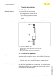
3 Product description 3 Scope of delivery 3.1 Configuration The scope of delivery encompasses: • Overvoltage arrester B63-48, B63-32 Documentation – this operating instructions manual – Ex specific safety instructions and, if necessary, further certificates • Constituent parts Product description The following illustration shows the structure of B63-48, B63-32: 1 2 3 Fig. 1: Structure of B63-48, B63-32 1 2 3 Application area 3.
3 Product description Packaging 3.3 Packaging, transport and storage Your instrument was protected by packaging during transport. Its capacity to handle normal loads during transport is assured by a test following ISO 4180. The packaging of standard instruments consists of environmentfriendly, recyclable cardboard. For special versions, PE foam or PE foil is also used. Dispose of the packaging material via specialised recycling companies.
4 Instructions for installation 4 Instructions for installation B63-48, B63-32 overvoltage arresters are screwed into the position of the cable gland on the sensor housing. The cable gland of the sensor is screwed into the overvoltage arrester. No further assembly is necessary. Caution: B63-48, B63-32 overvoltage arresters must not be used in a corrosive environment. The thread on the overvoltage arrester must correspond to the thread on the sensor housing.
5 Connecting to power supply 5 Note safety instructions Connecting to power supply 5.1 Preparing the connection Always keep in mind the following safety instructions: • Connect only in the complete absence of line voltage Danger: The stainless steel housing of B63-48, B63-32 has no electrical function and therefore provides no internal or external connection to ground or potential equalization.
5 Connecting to power supply 10. Push signal cables and screen through the cable gland and connect according to chapter "Wiring plan" to the terminals 11. Check all cable connections, especially the ground connection, to make sure they are tightened sufficiently 12. Insert terminal block into its position by using the pliers. A mechanical coding ensures the correct position 13. Screw cable gland into the thread of B63-48, B63-32, tighten compression nut.
5 Connecting to power supply Wiring plan 5.3 Wiring plan Display 1 2 5 6 7 I²C 8 1 Fig. 3: Wiring plan, sensor side, example single chamber housing Connection cables of B63-48, B63-32, wire assignment see chart Terminals sensor Wire colour/Polarity 1 Red (+) 2 Black (-) Ground terminal Green/yellow 1 + 1 G 2 Fig.
6 Maintenance and fault rectification 6 Maintenance and fault rectification 6.1 Maintenance If the instrument is used properly, no special maintenance is required in normal operation. To ensure the function of B63-48, B63-32, we recommend a regular visual check at intervals of max. 1 year for: • secure mounting mechanical damage or corrosion worn or otherwise damaged cables correct and clearly marked cable connections • • • 6.
7 Dismounting 7 Dismounting 7.1 Dismounting steps 7.2 Disposal Take note of chapters "Mounting" and "Connecting to power supply" and carry out the listed steps in reverse order. The instrument consists of materials which can be recycled by specialised recycling companies. We use recyclable materials and have designed the parts to be easily separable. WEEE directive 2002/96/EG This instrument is not subject to the WEEE directive 2002/96/EG and the respective national laws.
8 Supplement 8 Supplement 8.1 Technical data General data Version The device can be screwed into the sensor housing instead of the cable gland Housing material 316Ti Weight approx. 175 g (0.
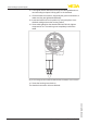
8 Supplement 8.2 Dimensions 76 mm (2.99") SW 27 mm (1.06") 250 mm (9.84") 56 mm (2.21") 1 Fig. 5: Dimensions B63-48, B63-32 Thread M20 x 1.
All statements concerning scope of delivery, application, practical use and operating conditions of the sensors and processing systems correspond to the information available at the time of printing. Subject to change without prior notice © VEGA Grieshaber KG, Schiltach/Germany 2013 VEGA Grieshaber KG Am Hohenstein 113 77761 Schiltach Germany Phone +49 7836 50-0 Fax +49 7836 50-201 E-mail: info.de@vega.com www.vega.