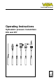
Level and Pressure Operating Instructions Hydrostatic pressure transmitters D76 and D77 p
Contents Contents Safety information ........................................................................ 2 Note Ex area ................................................................................ 2 1 Product description 1.1 Function and configuration .................................................. 4 1.2 Types and versions ............................................................. 4 1.3 Electronics version without adjustment .............................. 5 1.
Contents 3 Mounting 3.1 Mounting instructions ......................................................... 13 3.2 Compensation of the atmospheric pressure ................... 13 4 Electrical connection 4.1 Connection instructions ..................................................... 14 4.2 Terminal assignment .......................................................... 15 4.4 Connection examples ........................................................ 16 4.3 Connection to VEGABOX 01 ..........................
Product description 1 Product description 1.1 Function and configuration Adjustment The pressure transmitters D76 and D77 are efficient, modular instruments for hydrostatic level measurement. A dry, metallic-capacitive cell or the dry, ceramic-capacitive measuring cell CERTEC ® is used as pressure sensor element.
Product description 1.
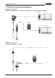
Product description 1.4 Electronics version with integrated adjustment in connection housing Electronics version D: Pressure transmitter 4 … 20 mA adjustable Adjustment in connection housing S Z ti Op 1 2 3 4 5 + - 4...20mA 12V...36V DC Bedieneinsatz operating unit PLC/DCS VEGABOX 01 S Z ti Op 1 2 3 4 5 + - 4...20mA 12V...36V DC Bedieneinsatz operating unit PLC/DCS 1.
Product description 2 Technical data 2.1 Data Supply and signal current circuit (analogue transmission, 4 … 20 mA) Power supply Residual ripple of the power supply Output signal - terminal insert - adjustment insert Current limitation Fault signal Integration time Average delay time Connection cable Max. permissible load 12 … 36 V DC no influence at USS < 100 mV analogue transmission (not standardised) 4 … 20 mA 4 … 20 mA (adjustable) approx.
Product description Measuring ranges Nominal meas. range Gauge pressure resistance D76 / D77 Low pressure resistance Gauge pressure 0 … 0.1 bar 10 bar / – -0.1 bar 0 … 0.2 bar 15 bar / – -0.2 bar • – 0 … 0.4 bar 20 bar / 10 bar -0.4 bar • • 0 … 1.0 bar 0 … 2.5 bar 25 bar / 25 bar 35 bar / 25 bar -1.0 bar -1.0 bar • • • • 0 … 5.0 bar 45 bar / 25 bar -1.0 bar • • 0 … 10.0 bar 60 bar / 25 bar -1.0 bar • • 0 … 20.0 bar 90 bar / 25 bar -1.
Product description Long-term stability Longterm drift of the zero signal 1) - D76 (ceramic measuring cell) - D77 (metallic measuring cell) < 0.1 %/year < 0.25 %/year Other actuating variables Calibration position Influence of the mounting location - ceramic measuring cell - metallic measuring cell Vibration resistance upright, diaphragm points downwards < 0.2 mbar < 5.0 mbar mechanical vibrations with 4 g and 5 … 100 Hz, tested acc.
Product description Materials, wetted parts Pressure transmitters D76 - transmitter - diaphragm - suspension cable cable bushing - measuring cell seal Pressure transmitters D77 - transmitter - diaphragm - suspension cable cable bushing Materials, non-wetted parts Pressure transmitters D76, D77 - housing - straining clamp - closing screw stainless steel 1.4571 ceramic (99.9 % Oxideceramic) PE-LD CSM Viton stainless steel 1.
Product description 2.
Product description VEGABOX 01 (connection housing with breather facility) 38 72 ø 5 Zum Anschluss an For connection to 135 TRANSMITTER + - 85 analog output 108 pressure transmitters with 118 Druckmessumformer mit analogem Ausgangsignal + VEGABOX 01 M20 x 1.
Mounting 3 Mounting 3.1 Mounting instructions 3.2 Compensation of the atmospheric pressure Cable entry The pressure transmitters can be mounted in any position. Cable entries must point downwards to avoid moisture ingress. For this purpose, the housing can be rotated by 330° in relation to the mounting part. A seal, appropriate for connection, must be used for mounting. This seal is either supplied with the pressure transmitter or must be provided by the customer.
Electrical connection 4 Electrical connection 4.1 Connection instructions The electronics in the pressure transmitter requires a supply voltage of 12 … 36 V DC. It is provided by two-wire technology, i.e. supply voltage and measuring signal are transmitted via the same two-wire connection cable. The supply voltage is provided via a power supply unit, e.g.: - power supply unit VEGASTAB 690 - processing unit with integrated DC current source (e.g.
Electrical connection ergy) must not connected in series. The special installation regulations (DIN VDE 0165) must be observed. Pressure transmitters in certain versions are equipped with a warning label, informing of measures to be taken to avoid electrostatic discharge. Keep the contents of the warning label in mind. Electronics version C 4 … 20 mA output signal 4-20mA + Control instrument 4 … 20 mA - 1 2 3 4 5 - + 4...20mA 12V...
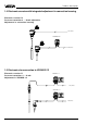
Electrical connection 4.3 Connection to VEGABOX 01 Zum Anschluss an For connection to Druckmessumformer mit Pressure transmitters with direct cable outlet Breather capillaries pressure transmitters with analogem Ausgangssignal Suspension cable analog output br + bl ge 1 2 10 11 12 3 + TRANSMITTER - - + VEGABOX 01 Screen + For supply or to the processing system - (4 … 20 mA, 12 … 36 V DC) Pressure transmitters with terminal insert in housing 4-20mA + - 1 2 3 4 5 - + 4...20mA 12V...
Electrical connection Powered by a VEGA signal conditioning instrument Standard wiring for nonstandardized output. Ammeter for local control + 1 - - 2 3 Pressure transmitter terminals 0/4 … 20 mA UH UK DISBUS Analogue transmission, not standardised ! Powered by a PLC with active input circuit Processing via PLC.
Setup 5 Setup 5.1 Sensor without adjustment Sensors with electronics version A and C have no adjustment possibility and are permanently adjusted to the stated measuring range. Procedure • Select the required function with the rotary switch. • With the "+“ and "–“ key you modify the signal current to the required values or set the suitable integration time. • Then, you set the rotary switch to position "OPERATE“.
Setup Adjustment information: - A modification of zero does not influence the adjusted span. - It is also possible to adjust currents for partial fillings, e.g. 8 mA for 25 % and 16 mA for 75 %. Then the electronics automatically calculates the current values for 0 % and 100 % (only possible with a difference ³ 3.3 %). - If the current values react to the key pressing with a time delay, there can be two reasons: - the last adjustment was carried out with a level deviating considerably from the actual level.
Diagnostics 6 Diagnostics 6.1 Maintenance Pressure transmitters D76 and D77 are maintenance-free. Checking electrical connections Pressure transmitter terminals Voltage 1 2 3 V Current mA External energy source - 6.2 Failure rectification Due to continuous self-monitoring, series D70 pressure transmitters offer maximum reliability. However, should failures occur, check the following before removing the pressure transmitter: - the atmospheric pressure compensation, - the electrical connections.
Instrument modification 7 Instrument modification 7.1 Retrofitting of adjustment insert Such a retrofitting can be necessary, e.g. if you want to adapt a pressure transmitter to different measurement conditions. Remove existing terminal insert 1 2 3 4 5 6 Disconnect pressure transmitter from power supply. Unscrew cover of the connection housing. Remove cover. Pull out connection cables from the terminal insert. Loosen the three screws on the terminal insert.
Notes 22 Pressure transmitters D76 and D77
Notes Pressure transmitters D76 and D77 23
VEGA Grieshaber KG Am Hohenstein 113 D-77761 Schiltach Phone (0 78 36) 50 - 0 Fax (0 78 36) 50 - 201 e-mail info@vega-g.de ISO 9001 The statements on types, application, use and operating conditions of the sensors and processing systems correspond to the latest information at the time of printing. Technical data subject to alterations 2.