Operating instructions Remote parameter adjustment and remote maintenance Configuration and connection Document ID: 23051 in Signal conditioning instruments and communication out
1 Introduction 1 Introduction The configuration, parameter adjustment, operation and measured value indication of all communication-capable VEGA instruments can be carried out via the adjustment software PACTware with respective DTM. Here, a PC is connected via an RS232, USB or Ethernet interface to the respective VEGA insturment. If there are none of these standard interfaces integrated in the respective VEGA instrument, connection must be provided via the interface converter VEGACONNECT.
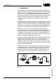
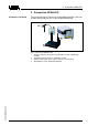
2 Connection plics® sensor 2 Connection plics® sensor Connection to the sensor (I²C) With this version, connection of VEGACONNECT 3 is carried out via the I²C interface integrated in the sensor. This is the easiest and fastest way to make a connection. The housing cover of the sensor cannot be closed when VEGACONNECT 3 is connected. Note: Use this connection variant only if the connection is to be short-term, in a dry environment and not in an Ex-area. 4 1 5 3 2 6 Fig.
2 Connection plics® sensor Information: With most PLC systems and other universal power supply units, this resistance must be used for communication. VEGAMET 381 (Ex), VEGADIS 371 (Ex), VEGATRENN 149 Ex are constructed in such a way that no additional resistance is required. With VEGAMET 624/625 and VEGASCAN 693, no communication is possible via the HART cable. Here, communication to the sensor is carried out via one of the integrated interfaces of the signal conditioning instrument.
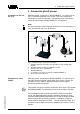
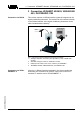
3 Connection VEGAMET 624/625, VEGASCAN 693, PLICSRADIO C62 3 Connection VEGAMET 624/625, VEGASCAN 693, PLICSRADIO C62 Connection via RS232 This version requires an RS232 interface (optional) integrated in the signal conditioning instrument. The modem can be connected directly to the RS232 interface of the signal conditioning instrument via the cable included with the delivery. 1 4 3 2 Fig.
3 Connection VEGAMET 624/625, VEGASCAN 693, PLICSRADIO C62 4 1 3 5 2 6 Fig. 5: Connection signal conditioning instrument via VEGACONNECT 3 1 Analogue telephone connection (not applicable in case of GSM radio modem) 2 Standard analogue modem or GSM radio modem 3 Special cable, art. no.: MODEM.
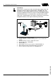
4 Connection VEGALOG 4 Connection VEGALOG Connection via RS232 The connection can be carried out via the RS232 interface in the front of either the VEGALOG CPU or the VEGACOM 557/558. 1 3 4 2 23051-EN-090302 Fig.
Printing date: VEGA Grieshaber KG Am Hohenstein 113 77761 Schiltach Germany Phone +49 7836 50-0 Fax +49 7836 50-201 E-mail: info@de.vega.com www.vega.com ISO 9001 All statements concerning scope of delivery, application, practical use and operating conditions of the sensors and processing systems correspond to the information available at the time of printing.