TH LINK Doc. Version 1.
Dear Customer, This installation Guide will help you to install the hardware. If you have any further questions, please contact our Technical Support: Trebing & Himstedt Prozeßautomation GmbH & Co. KG Technical Support Wilhelm-Hennemann-Str. 13 19061 Schwerin | Germany Phone: Fax: E-mail: Internet: +49 385 39572-500 +49 385 39572-22 support@t-h.de http://www.t-h.de All brand and product names are trademarks or registered trademarks of their respective owners.
Content About this Installation Guide .................................................................... 4 Intended use ............................................................................. 4 Explanation of safety instructions ............................................. 4 Menu and keyboard commands ................................................ 5 For your safety ......................................................................................... 5 Performance and functioning .............
About this Installation Guide About this Installation Guide Please read this installation guide carefully prior to installation. It facilitates installation and setup of your system and provides you with important information. Intended use The TH LINK is designed to be used as an interface between PROFIBUS and Ethernet networks. Any other use is deemed non-intended use.
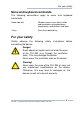
For your safety Menu and keyboard commands The following conventions apply to menu and keyboard commands: Courier font Window names, menu items, fields and descriptions of combo boxes, check boxes, radio buttons and icons. Press the indicated key. For your safety Strictly observe the following connecting the device: safety instructions before Danger! Small objects or liquids must not enter the case of the TH LINK (e. g. through the ventilation slots). This may damage the device.
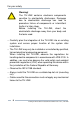
For your safety Warning! The TH LINK contains electronic components sensitive to electrostatic discharges. Damages due to electrostatic discharge can lead to premature failure of components or intermittent faults at a later stage. Before installing the TH LINK, divert the electrostatic discharge away from your body and the tools used. – Carefully plan the integration of the TH LINK into an existing system and ensure proper function of the system after installation.
For your safety – High temperature differences between the storage site and installation site can result in condensation within the case, which may cause the TH LINK to become damaged. In case of high temperature differences, please wait at least three hours before operating the TH LINK. – Lock the connected plug (PROFIBUS) using the srew connections intended for this purpose. Disposal The TH LINK must be disposed of separately from normal household waste in accordance with the 2002/96/EC (WEEE) directive.
Performance and functioning Performance and functioning The TH LINK provides access to the communication system and connects the higher-level network structure with the field level. It forms the basis for the Trebing + Himstedt products TH SCOPE, PROFIBUS Scope, Trebing + Himstedt DTM Library, TACC and TH OPC Server DP. The TH LINK is quick to assemble/install and to put into operation. The delivered default configuration allows start-up in only a few minutes.
Performance and functioning Configuration requirements (not included in the scope of delivery) – Web browser with Adobe Flashplayer 10.0 or higher – Enabling port 80 and IP 224.0.5.128 port 2364 UDP – Application software for PROFIBUS configuration Ethernet network presettings – The TH LINK is preset to Ethernet network operation with a DHCP server. No Ethernet network configuration settings are required in this operating mode.
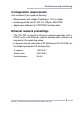
Design of the TH LINK Design of the TH LINK (see figure 1) 1 Ethernet interface 2 LED ETH 3 LED RUN 4 LED BUS 5 PROFIBUS interface 6 Terminal strip for power supply 7 Type label 8 Top-hat rail (not included in the scope of delivery) 10 Trebing & Himstedt Prozeßautomation GmbH & Co.
[2] [3] [4] [5] ETH [8] RUN BUS PROFIBUS [1] TREBING + HIMSTEDT Design of the TH LINK [6] [7] A B C D TH LINK Part No.: HW-Release: Serial No.: 10003006 2.0 000000 Temperature: 0 to +50 °C Current: 190 mA max. Power Supply: 19.2 to 28.8 V DC Made in Germany + – 24 V DC ETH: RUN: BUS: Ethernet (green/red) OK (green) | Error (red) PROFIBUS (green/red) www.t-h.de Trebing & Himstedt Prozeßautomation GmbH & Co. KG Fig.
Design of the TH LINK Connections and indicating elements [1] Ethernet interface: RJ-45 (10Base-T/100Base-TX) – LED lights yellow: Ethernet data communication – LED lights green: physical connection available [2] LED ETH – ETH lights red: first start phase – ETH flashes red: boot procedure – ETH lights red or flashes red or green in case of an error: internal firmware failure – ETH lights green: connection to application via Ethernet [3] LED RUN – RUN lights red: internal failure identified – RUN lights gr
Start-up guideline Start-up guideline The following steps are required for start-up: 1. 2. 3. 4. Install the TH LINK (see "Installing the TH LINK" on page 14). Connect to Ethernet (see "Connecting to Ethernet" on page 15). Connect to the power supply (see "Connecting the power supply" on page 16) Configure Ethernet (see "Configuring the TH LINK in the Ethernet network" on page 18) Note! To set the IP address manually you must connect your PC/notebook to the TH LINK via crossover cable. 5. 6.
Installing the TH LINK Installing the TH LINK Installing the TH LINK Warning! Above and below the TH LINK, a minimum of 2 inches head space for heat dissipation needs to be available. TH TH LINK LIN K Par t HW No.: Ser Releas 100 ial N e o.: : 2.0 03006 Tem 000 p 000 Cur eratu re: r Pow ent: 0 to er S +50 upp 1 9 °C 0 ly: 19.2 mA ma x. to 2 8 .
Connecting to Ethernet Uninstalling the TH LINK 1. 2. 3. Remove the connected supply and signal lines (Ethernet, PROFIBUS, voltage). Place the screwdriver into the stop lever on the TH LINK (see figure 2). Press the screwdriver in the direction of the TH LINK and simultaneously swing the device off the top-hat rail. Connecting to Ethernet – Insert the patch cable plug (RJ-45, not included in the scope of delivery) into the Ethernet socket (see figure 1 no.
Connecting the power supply Connecting the power supply Danger! Electrical voltage. Only qualified electricians are allowed to work on the electrical equipment. Danger! Incorrect TH LINK earthing can cause injury to personnel or device damage. Ensure correct and proper earthing of the TH LINK. Warning! Reverse polarity in the power supply can damage the device. Make sure the power supply is connected with correct polarity. 16 Trebing & Himstedt Prozeßautomation GmbH & Co.
Connecting the power supply +24 V 0 V not assigned Earth conductor Fig. 3: Terminal strip for power supply on the TH LINK 1. 2. Connect the cable of a 24 V power supply and the earth conductor (earth terminal) to the terminal strip on the device. The terminal strip can be plugged and lifted out for installation using a screwdriver. Switch on the power supply. The LED RUN is green and the LED ETH flashes red until the TH LINK's initiation procedure is completed. Afterwards only the LED RUN lights green.
Configuring the TH LINK in the Ethernet network Configuring the TH LINK in the Ethernet network Establish a connection to the TH LINK 1. 2. 3. Connect the TH LINK to a PC/notebook via crossover cable. The PC/notebook has to be in the same subnet as the TH LINK. Start a web browser on your PC/notebook. Enter the IP address http://169.254.0.1 and press . The TH SCOPE website is loaded. Login 1. 2. 3. Click on Login. Enter the password.
Configuring the TH LINK in the Ethernet network Settings Click on settings and then on TH LINK. Here you can change the settings for user administration, TH LINK description and network configuration. Fig. 4: TH LINK settings Note! For detailed information about each setting, click on the question mark. TH LINK | Trebing & Himstedt Prozeßautomation GmbH & Co.
Configuring the TH LINK in the Ethernet network User administration Here you can change the password. Proceed as follows: 1. 2. 3. Enter the old password. Select a new password and confirm it by re-entering. Finally, click Change password. TH LINK description Here you can enter a tag name, a location, an installation date and a description of the TH LINK. Network configuration Here you have to set the operation mode and the configuration method. You can also make time settings.
Configuring the TH LINK in the Ethernet network Configuration method (DHCP/Manual) There are two connecting options to choose from, depending on your network: – Connection in an Ethernet network with DHCP server – automatic and dynamic allocation of IP addresses (connection with patch cable via hub or switch) – Connection in an Ethernet network with manual IP address assignment (peer-to-peer) – manual allocation of IP addresses (connection with crossover cable) Connection in a network with DHCP (Dynamic Ho
Configuring the TH LINK in the Ethernet network Connection in a network with manual IP address assignment If you use the TH LINK in an Ethernet network without DHCP server, you need the following for configuration: – TCP/IP settings for this network – a PC/notebook with a web browser and Adobe Flash Player – a crossover cable between PC/notebook and TH LINK (peerto-peer connection) Note! Always notify your system administrator prior to allocating IP addresses.
Configuring the TH LINK in the Ethernet network Setting new IP and network addresses 1. Change the Configuration method from DHCP to Manual (see figure 5). Fig. 5: Setting IP and network addresses 2. Enter the new IP address. Note! Note down the set IP address. You can only access the TH LINK by using this IP address. 3. Enter the new addresses for Subnet mask and Default gateway. TH LINK | Trebing & Himstedt Prozeßautomation GmbH & Co.
Configuring the TH LINK in the Ethernet network 4. 5. If you want to use a DNS server, select Yes and enter the DNS server IP addresses. Click on the floppy disk sign to save the settings. Thereafter the TH LINK restarts and you will be logged out as administrator automatically. Note! If you use several TH LINK, you can facilitate the configuration by using the parameter distribution (see "Parameter distribution" on page 26).
TH SCOPE settings TH SCOPE settings Click on settings > TH SCOPE. Here you can change the settings for measurement, alert and parameter distribution. Fig. 6: TH SCOPE settings Note! Log in as administrator to change settings (see "Login" on page 18). Note! For detailed information about each setting, click on the question mark. TH LINK | Trebing & Himstedt Prozeßautomation GmbH & Co.
TH SCOPE settings Measurement The measurement settings include among other settings for baud rate and Start/Stop of the TH SCOPE measurement. Alert The alert settings include among other settings for activating the email alert function, when an email should be sent, SMTP server, subject, email sender and receiver. Parameter distribution The parameter distribution serves for a quick and easy configuration of several TH LINK. Therfore one TH LINK has to be set a parameter provider.
TH SCOPE settings Apply parameters By default all TH LINK are set as parameter receiver. Before taking over the parameters of a TH LINK, make sure that this TH LINK is set as a parameter provider. Click on Request at Apply parameters to query the parameters from the parameter provider. Thereafter the TH LINK restarts and you will be logged out as administrator automatically.
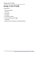
Connecting the PROFIBUS Connecting the PROFIBUS The 9-pin D-Sub socket is used for connection. – Only use standard PROFIBUS plugs and cables. – Wire the PROFIBUS plug according to the details for pin assignment (see "Technical data" on page 34). – If the TH LINK is installed at the beginning or end of the PROFIBUS cable segment, you will need a bus terminating resistor (see "Bus terminating resistors" on page 30). Warning! Do not use branch lines for the connection.
Connecting the PROFIBUS [1] [2] Ethernet THLINK LINK TH TH LINK Diagnostic Repeater PLC PROFIBUS DP PA Link Remote IO HART PROFIBUS PA Field Device Field Device Field Device Field Device Fig. 7: Interface connection possibilities in the PROFIBUS network [1] Connection behind a master (SPS) [2] Connection in a separate PROFIBUS segment behind a repeater. TH LINK | Trebing & Himstedt Prozeßautomation GmbH & Co.
Connecting the PROFIBUS Bus terminating resistors Terminations of a PROFIBUS segment must each be terminated with a bus terminating resistor. Use standardised plugs containing terminating resistors. +5 V DC/DC (Pin 6) Data+ (Pin 3) [1] Data– (Pin 8) [2] [3] GND DC/DC (Pin 5) Fig.
Firmware update Firmware update Firmware updates for the TH LINK are available free of charge at our website, www.t-h.de. Proceed as follows. 1. 2. 3. 4. 5. 6. You have to log in as administrator to perform a firmware update (see "Login" on page 18). Click on settings and then on Firmware update. Check if the requirements for a firmware update are met. Therefore the measurement and the external applikation must be stopped. Download the latest firmware version from www.t-h.
Troubleshooting Troubleshooting TH LINK is not found in the Ethernet network – Check the power supply (LED RUN must light green). – Check for correct connection (RJ-45, see "Connecting to Ethernet" on page 15). – The TH LINK is preset to network operation with a DHCP server (IP address for the TH LINK is assigned by the DHCP server).
Troubleshooting LED ETH lights red or flashes red or green in case of failure or LED RUN lights red – internal error – Internal error or defect: Please contact the Technical Support: Trebing & Himstedt Prozeßautomation GmbH & Co. KG Technical Support Wilhelm-Hennemann-Str. 13 19061 Schwerin | Germany Phone: Fax: E-mail: Internet: +49 385 39572-500 +49 385 39572-22 support@t-h.de http://www.t-h.de TH LINK | Trebing & Himstedt Prozeßautomation GmbH & Co.
Technical data Technical data Electrical data Nominal supply voltage (limit values) VDC 24 (19.2...28.8) Current consumption max. mA 190 Protection class IP 20 Operating conditions Ambient temperature range °F 32...122 Relative humidity % 20...80 (no condensation) Dimensions W × H × D in 0.9 x 3.9 x 4.5 Weight (approx.) l 0.3 Interface Type RS 485 Transmission rate bps 9,600...
General conditions General conditions Right to make additions or alterations Trebing & Himstedt Prozeßautomation GmbH & Co. KG reserves the right to continue development of this installation guide and the properties of the hardware and software at any time, also without releasing information about this or about alterations prior to doing so. Exclusion from liability Trebing & Himstedt Prozeßautomation GmbH & Co.
Doc.Nr. 10003010 © Trebing & Himstedt Prozeßautomation GmbH & Co.