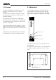
Level and Pressure Operating Instructions VEGACOM 557 PC/MODEM - Interface PC BA on 557 in out
Contents Contents Safety information ........................................................................ 2 Note Ex-area ................................................................................ 2 1 Product description 1.1 Configuration ........................................................................ 4 1.2 Functional principle .............................................................. 5 1.3 Function .................................................................................
Contents 5 Mounting and installation 5.1 Mounting and connection instructions ............................. 12 5.2 Mounting in carrier and housing ....................................... 13 6 Electrical connection 6.1 Connection instructions ..................................................... 14 6.2 Connection plans ............................................................... 14 7.1 Switch positions on VEGACOM 557 ................................. 15 7 Parameter adjustment of the interface .......
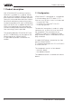
Product description 1 Product description With VEGACOM 557 an efficient interface converter is available. It is used for conversion of the VEGA-specific DISBUS and LOGBUS-interface to a RS232C-standard interface. Due to this, measured data and status information of level and pressure measuring systems can be transferred to a PC and visualised there with Visual VEGA (VV).
Product description VEGACOM 557 as LOGBUS-participant There is a permanent data exchange on the LOGBUS between the individual components of the VEGALOG 571. The VEGACOM 557 receives PC/PLC-telegrams containing measured values and status information as a participant of this LOGBUS. 1.2 Functional principle The gateway VEGACOM 557 can be integrated in two ways in level or pressure measuring systems: - as DISBUS-participant - as LOGBUS-participant. In both cases it is a passive participant.
Adjustment 1.3 Function 2 Adjustment The data of DISBUS or LOGBUS are firstly written in VEGACOM 557 into a buffer memory. From this buffer memory the data are read out by means of the Visual VEGA (VV) visualisation software. The indicating elements of VEGACOM 557 are located in the front plate of the component. LEDs are used as indicating elements signalling the operating condition (see page 9).
Adjustment 2.1 Configuration and parameter adjustment of connected measuring systems An additional function of VEGACOM 557 is the adjustment of the connected measuring system. The adjustment is made via a PC by means of the VEGA Visual Operating (VVO) adjustment software . The PC is connected via an interlink cable to the 9-pole SUB-Dplug in the front plate of VEGACOM 557.
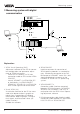
Measuring system 3 Measuring system with digital communication DISBUS Automatisation system 4 3 LOGBUS 1 5 4 5 1 2 Explanation: 1 VEGA Visual Operating (VVO) Adjustment software for the PC for convenient configuration and parameter adjustment of VEGA-instruments - VEGALOG 571 directly via RS 232connection cable to CPU-card or VEGACOM 557 - several VEGAMET via VEGACOM 557 or individually via VEGACONNECT - VEGASON, VEGAPULS via VEGACONNECT to the signal line or on the sensor 2 Visual VEGA (VV) Visual
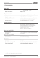
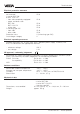
Technical data 4 Technical data Power supply Operating voltage Unom = 24 V AC (20 … 53 V), 50/60 Hz or = 24 V DC (20 … 72 V) approx. 6 VA 1 A, slow-blow Power consumption Fuse Electrical connection Component multiple plug acc. to DIN 41 612, series F 48-pole (d, b, z) with coding holes Module in carrier BGT 596 or BGT LOG 571 suitable multipoint connector acc. to DIN 41 612 with connection via standard technologies via screw terminals max.
Technical data Electrical protective measures Protection: not mounted in carrier BGT 596 or BGT LOG 571 - front side completely equipped - upper and lower side BGT 596 BGT LOG 571 - wiring side in housing type 505 - front side - other sides Protection class Overvoltage category IP 00 IP 40 IP 00 IP 20 IP 00 IP 40 IP 30 II (in housing type 505) II Electrical separating measures Reliable separation acc.
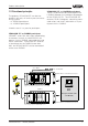
Technical data front RS232C interface Multiple plug 5 TE 128,4 LOGBUSplug 100 Multipoint connector 100 x 160 x 1,5 European size BA on 557 15 5,5 162 VEGACOM 557 - without protocol 25,4 11
Mounting and installation 5 Mounting and installation 5.1 Mounting and connection instructions The gateway VEGACOM 557 can receive measured data and status information in two different ways: - via the DISBUS (from measuring systems with VEGAMET) - via the LOGBUS (from measuring systems with VEGALOG).
Mounting and installation 5.2 Mounting in carrier and housing BGT 596 or BGT LOG 571 For mounting you just have to place a module in the requested position. A module consists of: - a multipoint connector acc. to DIN 41 612, series F, 33-pole (d, b, z) - two screws - three coded pins - two guide rails.
Electrical connection 6 Electrical connection 6.1 Connection instructions Interface cable PC – VEGACOM You should please note the following instructions for electrical connection: - the connection must be made according to the appropriate national installation standards (e.g. in Germany acc. to the VDEregulations). - the voltage supply of VEGACOM 557 must be made with low voltage to keep protection class II. When using VEGASTAB 593-60 or 593 a reliable separation of mains circuits acc.
Parameter adjustment of the interface 7 Parameter adjustment of the interface DIL-switch basic board 7.1 Switch positions on VEGACOM 557 ON A 6-pole DIL-switch block for adjustment of the RS 232 PC-interface in the front plate is located on the basic board. EDG Factory setting 1 2 3 4 5 6 Data format 8 data bits, 1 stop bit, even parity 8 data bits, 1 stop bit, no parity Before inserting VEGACOM 557 in the carrier or the housing, the DIL-switches have to be adjusted to the user specific data.
Set-up 8 VVO or VV in conjunction with VEGACOM 557 The configuration, parameter adjustment and adjustment of VEGA processing systems can be made with VEGA Visual Operating (VVO). For the visualisation of measured values the Visual VEGA (VV) software is available. For the use of VVO or VV a PC is connected with the RS232C-interface of VEGACOM 557. When this connection is not directly made via a cable, but by means of a modem via a telephone net, this is called remote parameter adjustment.
Connection examples 10 Connection examples The following connections between PC and VEGACOM 557 are possible to enable access to a VEGA processing system from a PC with VVO or VV via a VEGACOM 557. • PC on the front interface • Modem on the front interface 10.1 PC on the front interface In this example a PC is connected via the front interface of VEGACOM 557 with the VEGA processing system. The front interface is a RS232 C interface. Procedure: 1.
Notes 18 VEGACOM 557 - without protocol
Notes VEGACOM 557 - without protocol 19
VEGA Grieshaber KG Am Hohenstein 113 77761 Schiltach/Germany Phone +49 (0) 7836 50-0 Fax +49 (0) 7836 50-201 E-Mail info@de.vega.com www.vega.com ISO 9001 The statements on types, application, use and operating conditions of the sensors and processing systems correspond to the actual knowledge at the date of printing. Technical data subject to alteration.