
Manual

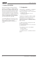

6 VEGACOM 557 - without protocol
Adjustment
on
557
BA
PC
!
Voltage supply
Fault signal
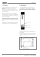
2 Adjustment
The indicating elements of VEGACOM 557
are located in the front plate of the compo-
nent. LEDs are used as indicating elements
signalling the operating condition (see page
9).
1.3 Function
The data of DISBUS or LOGBUS are firstly
written in VEGACOM 557 into a buffer
memory.
From this buffer memory the data are read
out by means of the Visual VEGA (VV) visu-
alisation software.
By means of the VEGA Visual Operating,
(VVO) parameter adjustment or configuration
of connected level and pressure measuring
systems is possible.
The communication can be made via a PC or
modem to the remote PC (remote parameter
adjustment) directly connected to VEGACOM
557.
The data communication between VEGACOM
557 and the PC is always initiated by the PC.
without function
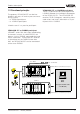
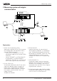
The adjustment elements are located on the
basic board.
A 6-pole DIL-switch block on the basic board
is used for adjustment of the front PC-inter-
face.
Basic board
Additional
board
DIL-switch
on the basic board